
Operation input device and electronic equipment employing the same

a technology of input device and electronic equipment, applied in the direction of mechanical control device, manual control with single control member, instruments, etc., can solve the problem of not achieving smooth turning operation, and achieve the effect of smooth turning operation

Inactive Publication Date: 2006-12-14
ORMON CORP
View PDF20 Cites 30 Cited by
  • Summary
  • Abstract
  • Description
  • Claims
  • Application Information

AI Technical Summary

Benefits of technology

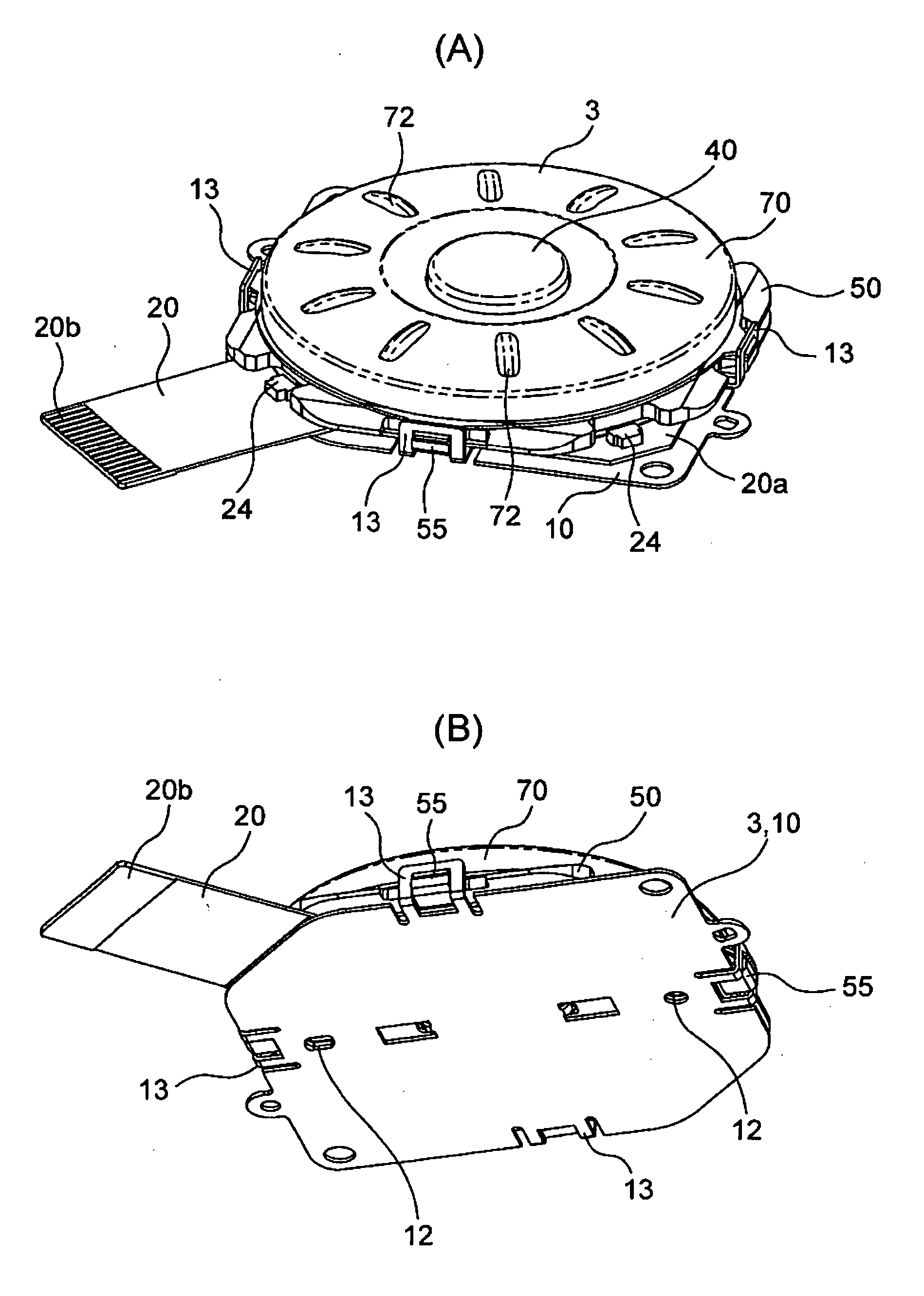
The present invention provides an operation input device with good operation feeling that removes the vertical ricketiness of an operation dial and ensures a smooth turning operation. The device includes a base, a printed circuit board with pushbutton switches and magnetic field detecting elements, an operation plate, a disc type operation dial, and a flexible slide sheet. The operation dial is turnably assembled on the operation plate, and the slide sheet is supported by the base and urges the operation plate downwards. The operation plate is pushed upwards to prevent maloperation and can be pushed up by elastic arms or elastic pads. The invention allows for a smooth turning operation without vertical ricketiness and improves the operation feeling of the device.

Problems solved by technology

This leads to the problem that a smooth turning operation is not attained.

Method used


Image

  • Operation input device and electronic equipment employing the same
  • Operation input device and electronic equipment employing the same
  • Operation input device and electronic equipment employing the same

Examples


second embodiment

[0064] the operation plate 50 is pushed upwards, so that superfluous loads do not act on pushbutton switches 29a-29e, and any maloperation can be prevented. Moreover, since elastic arms being separate members are not required, the number of components and the number of assembling man-hour are small, and an operation input device of high productivity is obtained.

[0065] As shown in FIG. 14A through FIG. 17, the third embodiment of the invention corresponds to a case where elastic pads 34 are respectively placed on pushbutton switches 21a-21e through a resin-made film cover 30. Incidentally, the same parts as in the first embodiment are assigned the same reference numerals and signs, and they shall be omitted from description. For the brevity of illustration, however, the resin-made film cover 30 is not shown in FIGS. 14A through 15C.

third embodiment

[0066] the elastic pads 34 are placed so as to push an operation plate 50 upwards, whereby the operation plate 50 can be prevented from becoming rickety in a vertical direction. Especially, since the elastic pads 34 can absorb a cumulative error ascribable to the assemblage of a large number of components, a high assemblage precision is not required, and an operation input device easy of fabrication is obtained.

[0067] Incidentally, FIG. 18 illustrates the principle stated above. Elastic members urging the operation plate 50 in the figure correspond to the slide sheet 60, elastic arms 14 and elastic pads 34 in the respective embodiments stated above.

[0068] Besides, the ricketiness may well be prevented in such a way that the elastic pads are arranged between the upside of the printed circuit board 20 and the underside of the operation plate 50 so as to urge this operation plate 50 upwards.

[0069] It is a matter of course that the operation input device according to the invention is...


PUM


Abstract

An operation input device includes a base, a printed circuit board which has a plurality of pushbutton switches and Hall elements mounted on its upside and which is stacked on and united with the base, an operation plate which is supported on the base so as to be vertically movable on the printed circuit board, and a disc type operation dial in which an annular magnet with N-poles and S-poles arranged alternately is assembled on the underside of this operation dial and which is turnably assembled on the upside of the operation plate. Here, the disc type operation dial is turned, thereby to sense the changes of the magnetic fluxes of the annular magnet by the Hall elements and to detect a turning direction, while the disc type operation dial is depressed, thereby to operate any of the pushbutton switches through the operation plate. The operation dial is prevented from becoming rickety in a horizontal direction, and it ensures a smooth turning operation, thereby to afford a good operation feeling.

Description

BACKGROUND OF THE INVENTION 1. Field of the Invention [0001] The present invention relates to an operation input device which is applicable to a portable telephone or a portable music player. 2. Description of the Related Art [0002] Heretofore, an operation input device for use in a portable telephone or the like has been, for example, one including a base, a printed circuit board which has a plurality of pushbutton switches and magnetic field detecting elements mounted on its upside and which is stacked on and united with the base, an operation plate which is placed on the printed circuit board, and a disc type operation dial in which an annular magnet with N-poles and S-poles arranged alternately is assembled on the underside of the operation dial and which is turnably assembled on the operation plate. With the operation input device, the operation dial is turned, whereby the changes of the magnetic fluxes of the annular magnet are sensed by the magnetic field detecting elements s...

Claims


Application Information

Patent Timeline
Patent Type & Authority Applications(United States)
IPC IPC(8): H01H9/00G06F3/0338G06F3/0362
CPCG06F3/0338G05G9/047G06F3/0362B66C13/44B66C13/063B66C2700/08
Inventor MIYASAKA, TAKESHIMIYOSHI, KAZUAKI
Owner ORMON CORP
Learn More