
Data Transmission System for Computer Tomographs

a technology of data transmission system and computer tomograph, which is applied in the field of data transmission system, can solve the problems of easy interference in the transmission system, and achieve the effect of small mechanical outlay

Active Publication Date: 2006-12-07
SCHLEIFRING & APPBAU
View PDF20 Cites 17 Cited by
  • Summary
  • Abstract
  • Description
  • Claims
  • Application Information

AI Technical Summary

Benefits of technology

[0007] It is the object of the invention to provide a computer tomograph having a data transmission system that is substantially non-sensitive to mechanical tolerances and can be incorporated in a computer tomograph with small mechanical outlay.

Problems solved by technology

When incorporated into existing slip-rings, these transmission systems are easily subject to interference from adjacent energy transmission tracks.

Method used


Image

  • Data Transmission System for Computer Tomographs
  • Data Transmission System for Computer Tomographs

Examples


Embodiment Construction

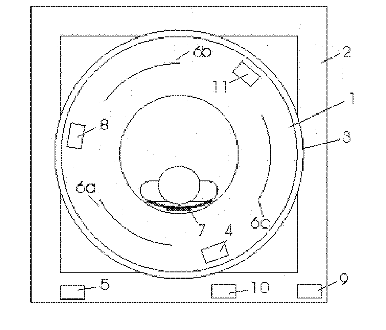
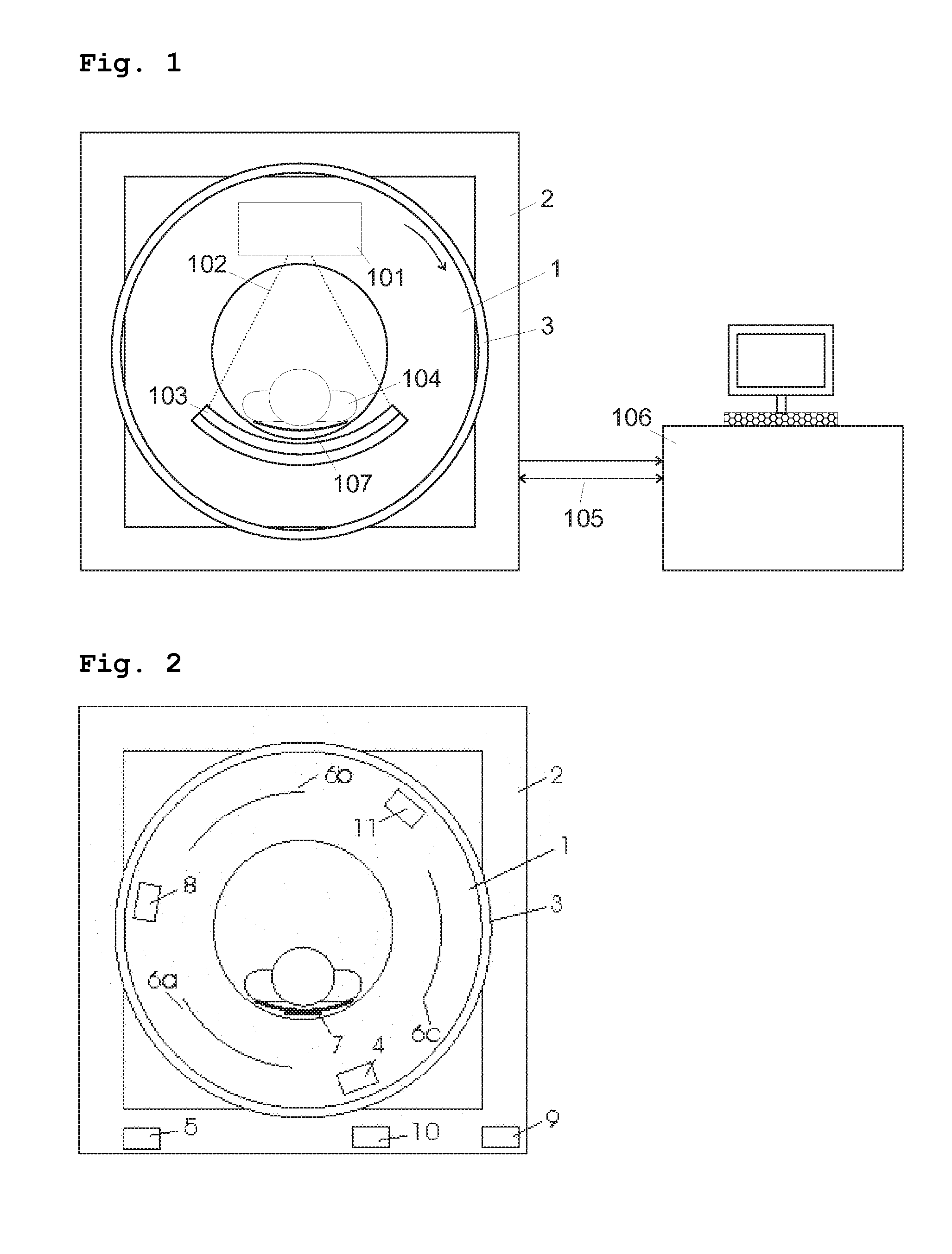
[0012] A computer tomograph in accordance with the invention, having a system for transmitting data between a rotating part and a stationary part, comprises at least one data source on the rotating part, and at least one data sink on the stationary part. A data source may be, for example, an X-ray detector or its DAS (data acquisition system), or also any other control means or computers. A data sink may be a computer for evaluating and processing the data, but also another control unit.

[0013] Furthermore, at least one first transmitter means and also a transmitter antenna arrangement fed thereby are provided in the rotating part. A first transmitter means of this kind receives data from the data source and converts them for emission by the transmitter antenna arrangement. Moreover, at least one first receiver means is provided in the stationary part to be fed by a receiver antenna arrangement. The receiver means converts the signals received from the receiver antenna arrangement f...


PUM


Abstract

A computer tomograph comprises a rotating part and a stationary part, and includes a system for transmitting data between the rotating part and the stationary part with a directional radio link. The system comprises an antenna arrangement for directional emission of data signals from the rotating part along a direction of a rotation axis of the rotating part, and for directionally sensitive reception of data signals at a patient's table on the stationary part.

Description

PRIORITY CLAIM [0001] This application claims priority to German Application No. 10 2005 026 158.2 filed Jun. 6, 2005. BACKGROUND OF THE INVENTION [0002] 1. Field of the Invention [0003] The invention relates to a data transmission system for transmitting data between a rotating part and a stationary part of a computer tomograph by means of directed radio transmission. [0004] 2. Description of the Prior Art [0005] A device for data transmission in computer tomographs is known from U.S. Pat. No. 6,433,631. A transmitter signal is made to impinge on a strip conductor line in a rotating part. A tap provided on a stationary part is kept at a small distance of an order of magnitude of about 1 mm from the strip conductor line. [0006] Usually the transmission systems known from prior art can be incorporated in computer tomographs or their rotary joints only at large expenditure of means. Thus, they may be assembled to form independent units, but for this they need a support along the circu...

Claims


Application Information

Patent Timeline
Patent Type & Authority Applications(United States)
IPC IPC(8): H04L27/00
CPCA61B6/56A61B6/03
Inventor SCHILLING, HARRY
Owner SCHLEIFRING & APPBAU
Learn More