
Object graph editing context and methods of use

a graph and context technology, applied in the field of object-oriented application programming environments, can solve the problems of not creating a functional program, single database application program cannot generally be used with different databases, and application programs for even this simple function are complicated

Inactive Publication Date: 2006-11-30
NEXT
View PDF0 Cites 52 Cited by
  • Summary
  • Abstract
  • Description
  • Claims
  • Application Information

AI Technical Summary

Benefits of technology

"The present invention is a system for managing changes to a graph of data bearing objects. It uses a data graph manager object to identify changes made to enterprise objects and notify other objects when changes occur. The system records snapshots of objects before and after changes, allowing for event-based undo capabilities. It also monitors the creation of new enterprise objects to prevent conflicts with existing ones. Multiple levels of editing contexts are used to create isolated object graphs, allowing for independent manipulation of the underlying data bearing objects. Overall, the system provides efficient and flexible management of changes to a data graph."

Problems solved by technology

Although objects are generally internally self-reliant, and can therefore be viewed as modules that can be assembled with other objects into a variety of application programs, the simple assembling of objects does not create a functional program.
As these can vary from one database to another, a single database application program cannot generally be used with different databases.
The application program for even this simple function is complicated: the program must know about the structure of the tables in the database, must be able to generate a variety of database requests in the particular syntax of the database management program, must be able to process the data received, and must be able to assemble the data and display it on a user interface.
This requirement requires additional code in each enterprise object, making the building of enterprise objects, and applications using enterprise objects, more complicated and time consuming than other kinds of object oriented programming.
Another limitation of Enterprise Objects Framework 1× is that because controller 140 is tightly coupled to user interface 160, controller 140 is not usable for database server and other non-user interface applications.

Method used


Image

  • Object graph editing context and methods of use
  • Object graph editing context and methods of use
  • Object graph editing context and methods of use

Examples


Embodiment Construction

[0040] In the following description, numerous specific details are set forth in order to provide a thorough understanding of the present invention. It will be apparent to one skilled in the art, however, that the present invention may be practiced without these specific details. In other instances, well-known features have not been described in detail in order not to unnecessarily obscure the present invention.

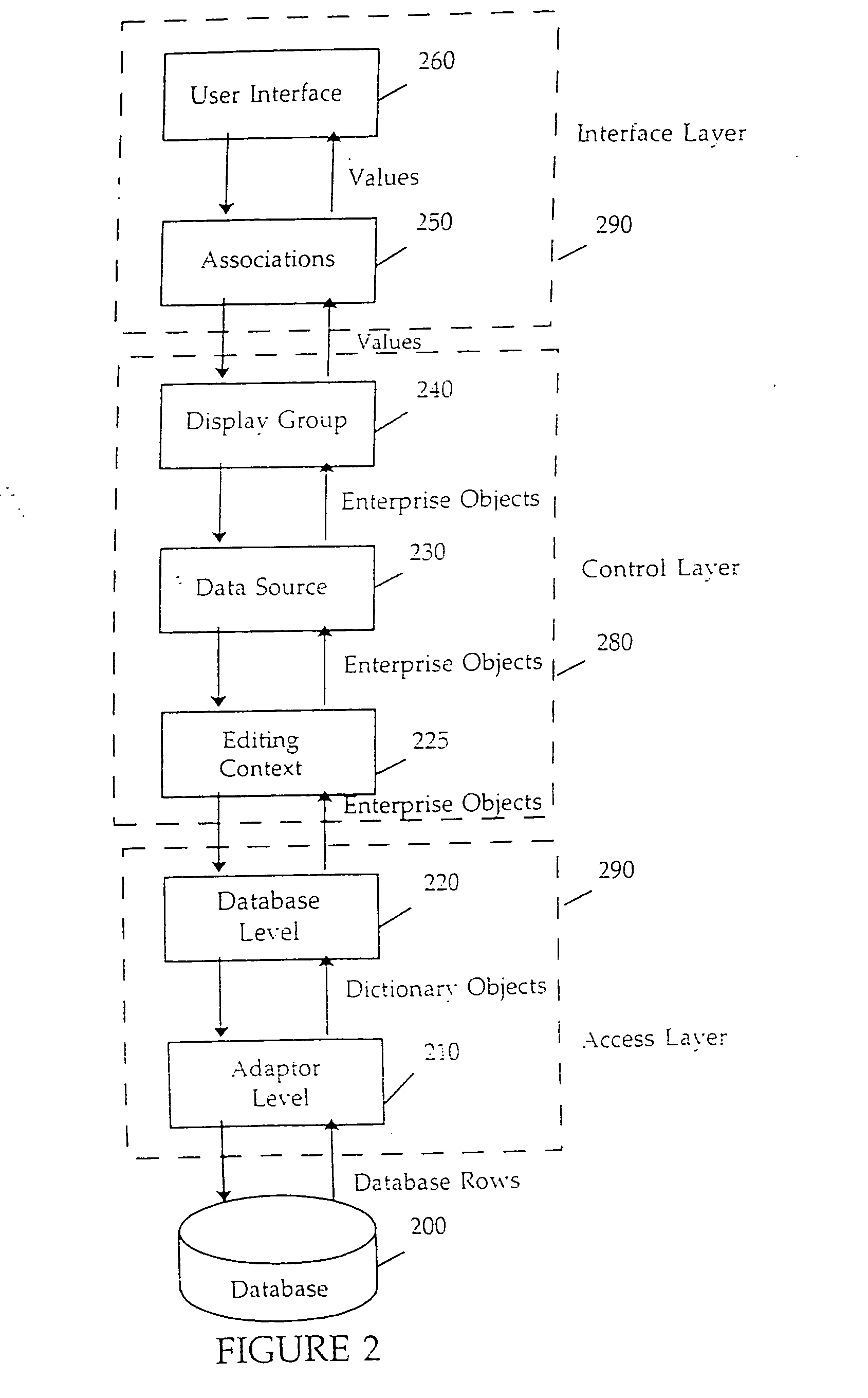
[0041] The general structure of one embodiment of a database application program-utilizing the present invention is shown in FIG. 2. This embodiment is used in the Enterprise Objects Framework 2.0 database application programming package from NeXT Software, Inc., assignee of the present invention. Enterprise Objects Framework 2.0 is described in the Enterprise Objects Framework Developer Guide, preliminary release, attached hereto as Appendix A.

[0042] In the application shown in FIG. 2, like in the prior art application shown in FIG. 1, data flows from a relational database ...


PUM


Abstract

The present invention comprises a novel system for managing changes to a graph of data bearing objects. In one embodiment, an object graph manager object referred to as an editing context is used to identify changes made to data bearing enterprise objects and to notify other interested objects when changes occur. As a result, data bearing objects need not themselves contain code necessary for monitoring changes. In another embodiment of the invention, the editing context is used to provide event-based “undo” capabilities. In another embodiment of the invention, each enterprise object has a primary key that is used to maintain the identification between an enterprise object instance and a corresponding database row. In another embodiment of the invention, multiple levels of editing contexts are used to provide multiple isolated object graphs, each of which allows independent manipulation of the underlying data bearing objects.

Description

BACKGROUND OF THE INVENTION [0001] 1. Field of the Invention [0002] The present invention relates to the field of object oriented application programming environments, particularly for applications accessing databases. [0003] 2. Background Art [0004] Object oriented programming languages are non-procedural programming languages in which program elements are viewed as objects that can pass messages to each other. An object includes its own data and programming code and is internally self-reliant. The programming code of an object includes procedures or methods. The methods of an object are invoked by messages received from another object. Each object is an instance of an object class. The properties of the objects in a class are defined by a class definition. A class definition may utilize a hierarchical class structure in which objects in the class inherit properties of a parent class in addition to properties explicitly defined for the class. This inheritance property allows code f...

Claims


Application Information

Patent Timeline
Patent Type & Authority Applications(United States)
IPC IPC(8): G06F7/00G06F17/00G06F17/30G06K17/00
CPCG06F8/24G06F17/30306G06F17/30368G06F17/30569Y10S707/99944Y10S707/955Y10S707/99943Y10S707/99953Y10S707/99945G06F17/30607G06F16/2358G06F16/258G06F16/289G06F16/217
Inventor FEDERIGHI, CRAIGWILLHITE, DANNOYAU, ERIC
Owner NEXT
Learn More