
Method and device for transponder aided wake-up of a low power radio device

a radio device and low-power technology, applied in the direction of current supply arrangement, power management, high-level techniques, etc., can solve the problems of limiting factors such as power consumption, power consumption, and the average power consumption of the beacon for operation, and achieve the effect of increasing the sensibility of the detector

Inactive Publication Date: 2006-11-30
NOKIA CORP
View PDF11 Cites 106 Cited by
  • Summary
  • Abstract
  • Description
  • Claims
  • Application Information

AI Technical Summary

Benefits of technology

[0025] The scanning duration is related to the time wherein a measurement is possible, before the device enters the passive mode. To reduce the number of energy measurements, only one energy measurement can be executed in each scanning cycle. To enable a set of measurements, the device can use a number of successive scanning duration to execute a number of energy measurements.
[0060] In another example embodiment said low power radio device further comprises an amplifier connected between said antenna and said antenna switch. This embodiment enables the device to increase the sensibility of said detector to weak radio signals, without the need to operate the receiver stage of said transceiver.

Problems solved by technology

This beacon like solution has the disadvantage that independent from the actual use, the operation time is limited by the battery power and the average power consumption for operation of the beacon.
The power consumption is the critical element of battery powered devices that use a short range radio link.
Thus, the device is using some power in trying to setup a connection even if there are no other devices in the vicinity and the lifetime of the battery becomes a limiting factor.
Unfortunately, if only RF front end and LNA were activated all energy inside the band filter would be included in the RSSI measurement and e.g. in the 2.4 GHz ISM a microwave oven could turn the device active continuously, i.e., the power efficiency gain is lost.
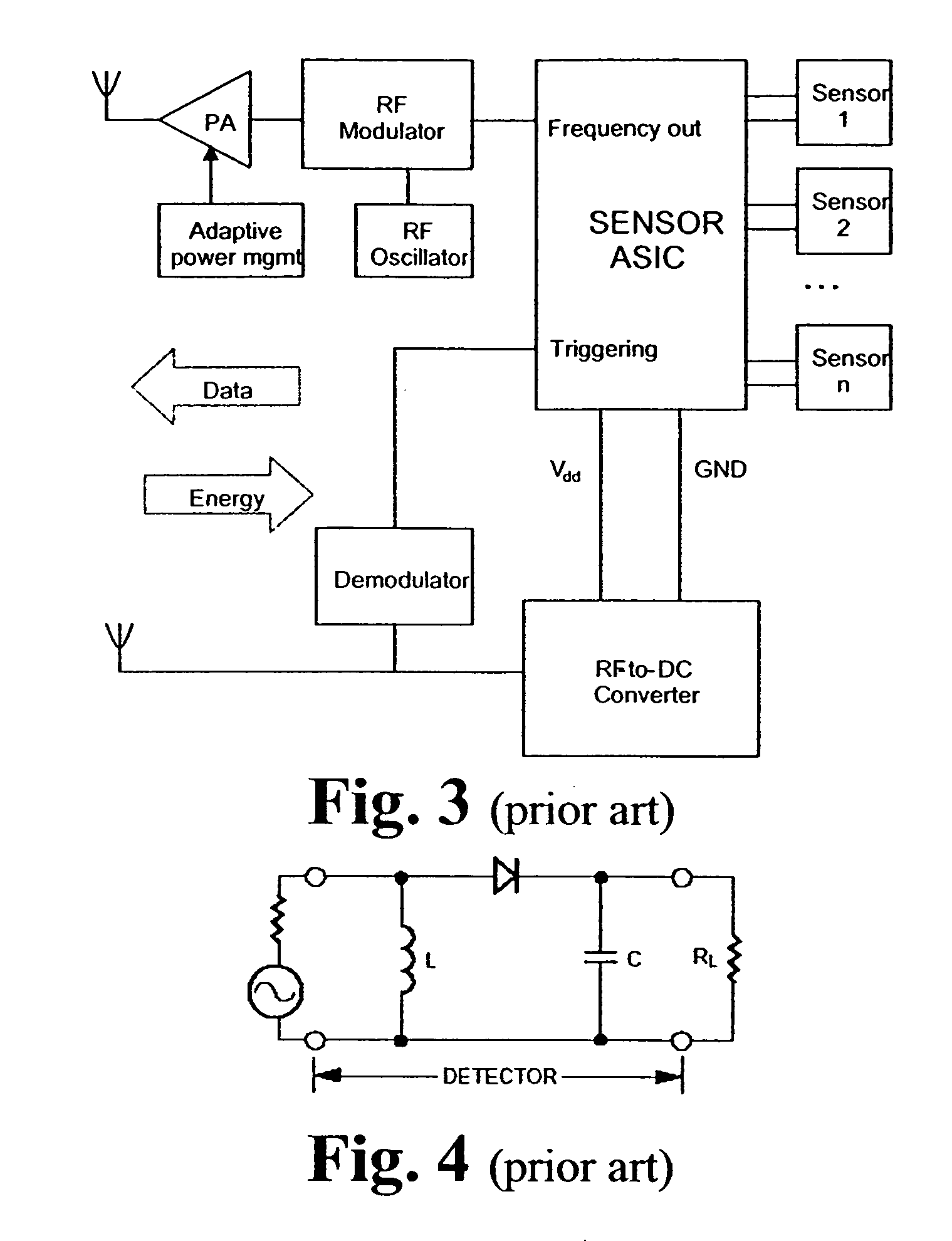
One problem is that the transponder (or other sensor) may activate from any energy on the frequency band such as other Bluetooth- / WLAN—(Wireless Local Area Network) / ISM—(Industrial, Scientific, and Medical Frequency band at 2.4 GHz) devices, microwave ovens etc.
The state of the art does not provide a solution that can be applied in urban as well as in the country i.e. in highly and lowly radio frequency polluted areas.
All the above approaches for a wake up and communication setup are not suitable for the use environments in which the ISM band activity is not known.

Method used


Image

  • Method and device for transponder aided wake-up of a low power radio device
  • Method and device for transponder aided wake-up of a low power radio device
  • Method and device for transponder aided wake-up of a low power radio device

Examples


Embodiment Construction

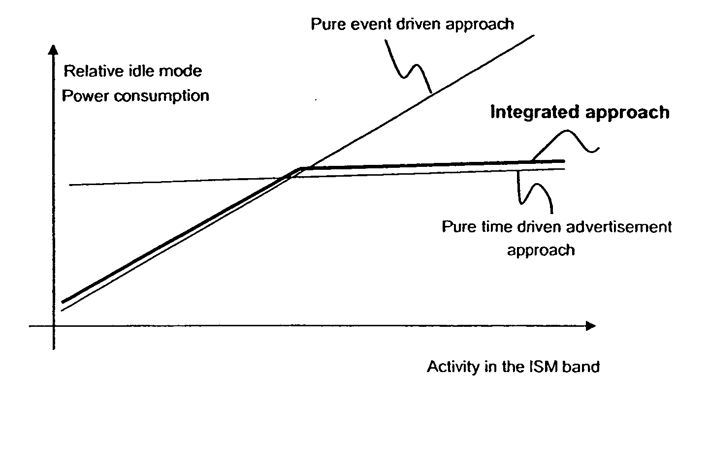
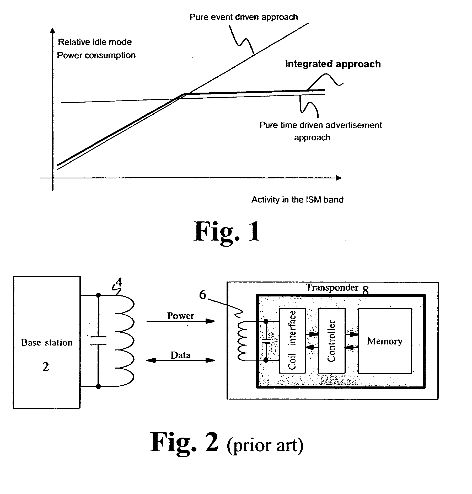
[0080]FIG. 1 illustrates the benefit of the invention compared to a purely time driven and a purely event driven approach. The actual shape of curves and differences between curves depend on various implementation parameters, usage scenarios and environment.

[0081]FIG. 2 is a block diagram of a transponder according to the state of the art. The conventional transponder 8 comprises an antenna depicted as the coil 6 connected to an antenna interface. The antenna interface is connected to a controller which is in turn connected to a data storage. In the figure there is also a depicted a base station 2 with an antenna 4. The standard operation of the system is that the transponder is waiting for an incoming message received via the antenna 6. In response to an incoming message the controller retrieves data from a memory and transmits the data via the antenna 6. In the present example the transponder is powered by radio energy received via the coil 6 and rectified in the coil interface. ...


PUM


Abstract

A method, software tool, computer program product and low power radio device are provided for transponder aided wake-up and connection set-up by detecting a wake up event in a sleep mode of the low power radio device, putting the radio device into an operative state, transmitting at least one advert message by radio transmission, wherein the low power radio devices put into a passive mode for a predetermined period of time in case no answer is received in response to the at least one transmitted advert message.

Description

CROSS-REFERENCE TO RELATED APPLICATION [0001] This application is a continuation of U.S. patent application Ser. No. 10 / 279,741 filed Oct. 22, 2002.BACKGROUND OF THE INVENTION [0002] The invention relates to setting up a connection between two wireless low-power devices. When two devices want to connect to each other some kind of notification of the need for connection must be made. Devices may signal their need all the time or every now and then. Compromises must be made to save batteries power, especially in small, simple devices meant for goods for sale. For example a CD-disc might have a small electronic chip in its cover and when a customer wants to know more about the CD he would get a URL to his Bluetooth device from the chip. [0003] This problem can be solved by a system where all devices send advertising signals periodically and they listen on the same frequency for a while for reply (time driven). In this case the device, which sends the reply message, communicates the nee...

Claims


Application Information

Patent Timeline
Patent Type & Authority Applications(United States)
IPC IPC(8): H04B1/16H04M1/73H04W52/02H04W88/02
CPCH04W52/0229Y02B60/50H04W88/02Y02D30/70
Inventor LAPPETELAINEN, ANTTIRYHANEN, TAPANIHONKANEN, MAURIHYYRYLAINEN, JARI
Owner NOKIA CORP
Learn More