
RF Powered Remote Control

a remote control and radio frequency identification technology, applied in the field of electronic devices, can solve problems such as unauthorized access to personal data and other information stored in the rfid tag

Inactive Publication Date: 2006-11-30
COLBY TRUST STEVEN M +1
View PDF14 Cites 74 Cited by
  • Summary
  • Abstract
  • Description
  • Claims
  • Application Information

AI Technical Summary

Problems solved by technology

A problem with using RFID tags to store security, confidential and / or personal information is that an RFID reader can read any RFID tags that pass within its range.
Even if data is encrypted, this creates a possibility of unauthorized access to the personal data and other information stored in the RFID tag.

Method used


Image

  • RF Powered Remote Control
  • RF Powered Remote Control
  • RF Powered Remote Control

Examples


Embodiment Construction

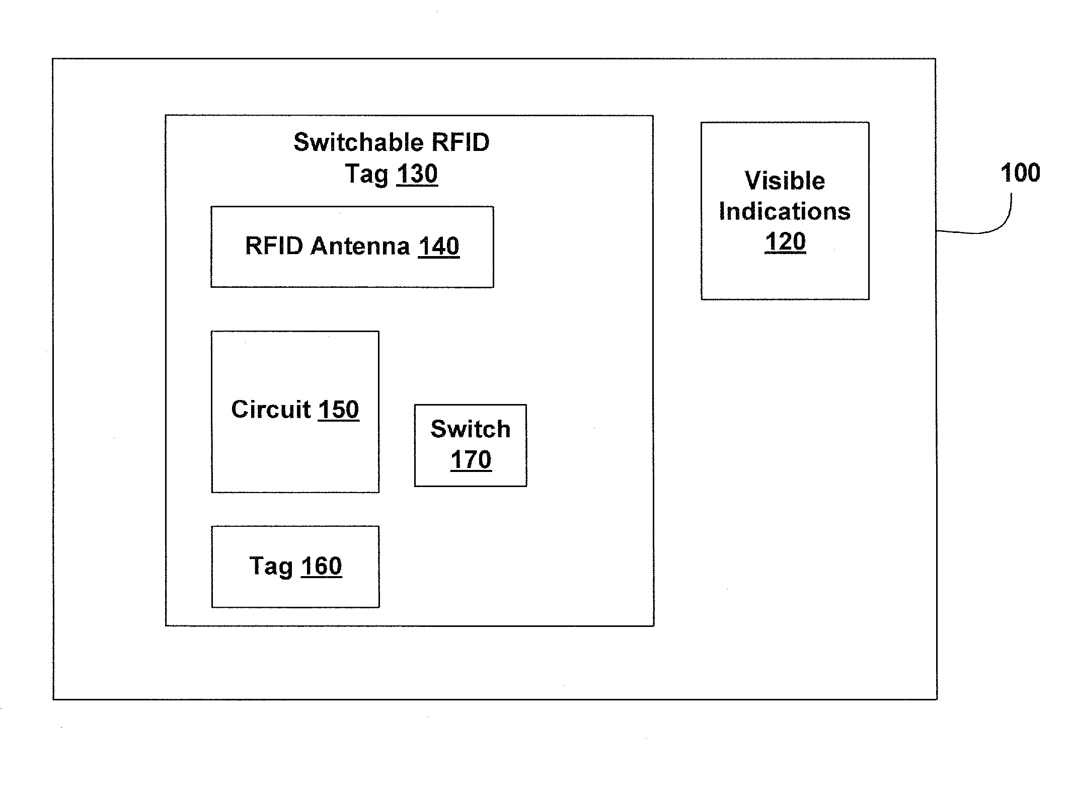
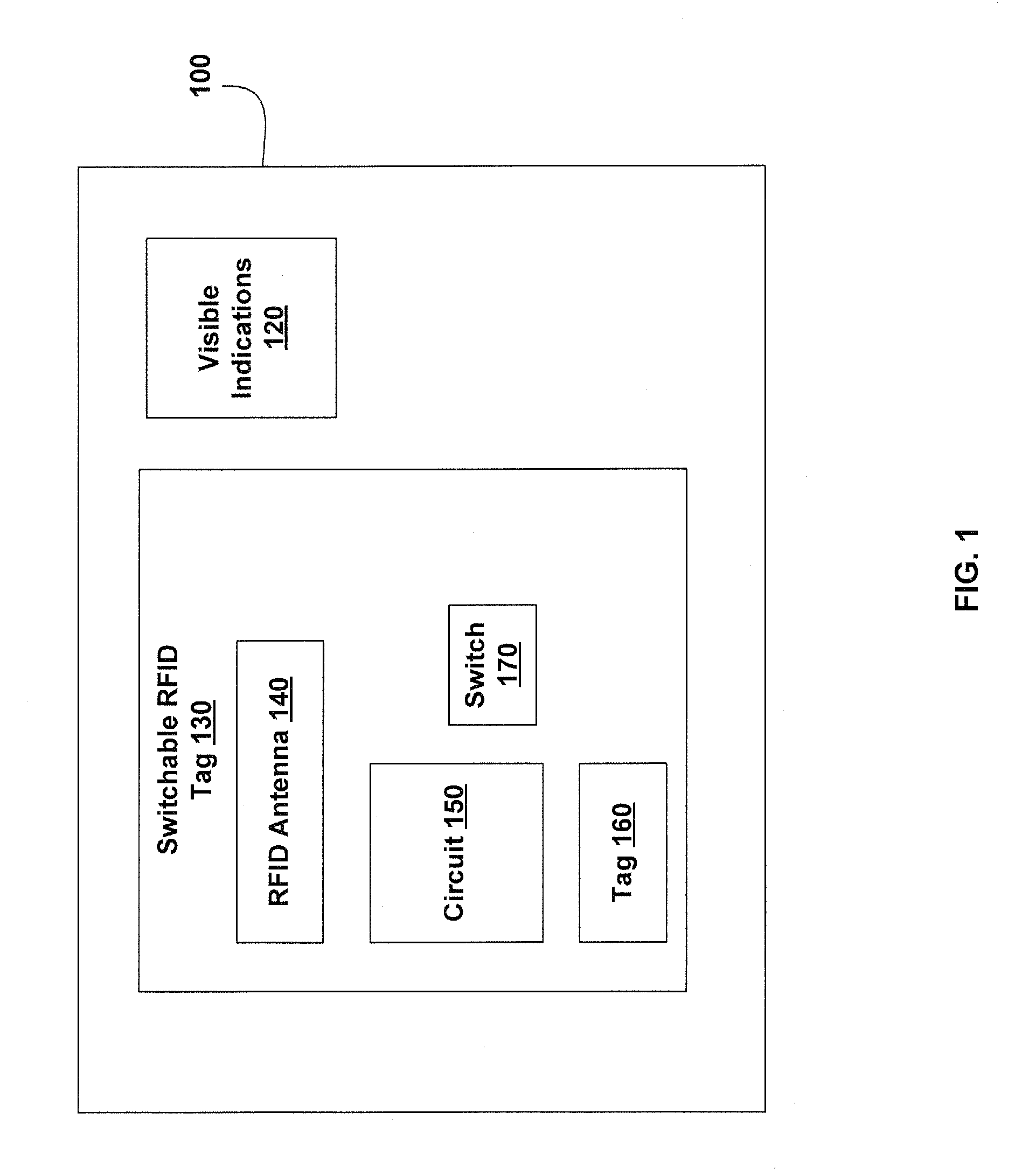
[0055]FIG. 1 is a block diagram of a Switchable RFID Device 100. In some embodiments, Switchable RFID Device 100 is an identity device such as a passport, identity card, driver's license, immigration document (e.g., green card or visa), student identity card, library card, financial card (e.g., credit card, debit card or prepaid card), social security card, Military ID card, key, keycard or the like. Switchable RFID Device 100 optionally includes Visible Indications 120 such as a barcode, picture, image, name, address, text, and / or the like. Switchable RFID Device 100 further includes one or more Switchable RFID Tag 130. Switchable RFID Tag 130 includes one or more RFID Antenna 140, a Circuit 150, one or more Tag 160 and one or more Switch 170. Switch 170 is optionally disposed within Circuit 150 or Tag 160. RFID Antenna 140 is configured for sending a radio frequency (RF) signal from Switchable RFID Device 100 in response to a received signal. The received signal is optionally used...


PUM


Abstract

Various passive remote control devices are disclosed. These passive remote control devices may include one or more RFID tags and one or more switches. In various embodiments, the passive remote control devices include identity devices, financial devices remote controls, and the like. The devices controlled may include electronic devices, televisions, computers, locks, physical access systems, or the like. In some embodiments, switches are configured to enter data into a switchable RFID device, for example to select a financial account.

Description

CROSS REFERENCE TO RELATED APPLICATIONS [0001] This application is a continuation-in-part of U.S. patent application Ser. No. 11 / 382,265 Filed May 8, 2006; this application also claims benefit and priority to U.S. provisional patent applications: 60 / 678,428 filed May 6, 2005; 60 / 685,331 filed May 27, 2005, 60 / 700,884 filed Jul. 19, 2005; 60 / 712,308 filed Aug. 30, 2005; 60 / 715,641 filed Sep. 10, 2005; 60 / 752,933 filed Dec. 21, 2005; 60 / 758,751 filed Jan. 13, 2006; 60 / 782,068 filed Mar. 13, 2006; 60 / 744,154 filed Apr. 3, 2006, and 60 / 746,636 filed May 6, 2006. The disclosures of the above provisional patent applications are hereby incorporated herein by reference. [0002] The disclosure of U.S. nonprovisional patent application Ser. No. 11 / 350,309 filed Feb. 7, 2006 is hereby incorporated herein by reference.BACKGROUND OF THE INVENTION [0003] 1. Field of the Invention [0004] The invention is in the field of electronic device and more specifically in the field of radio frequency identif...

Claims


Application Information

Patent Timeline
Patent Type & Authority Applications(United States)
IPC IPC(8): H04Q5/22
CPCG06K19/0707G06K19/0723G06K19/0712
Inventor COLBY, STEVEN M.
Owner COLBY TRUST STEVEN M
Learn More