Universal signal modulators
a signal modulator and universal technology, applied in the field of digital signal modulators, can solve problems such as the substitution of a different modulator structur
- Summary
- Abstract
- Description
- Claims
- Application Information
AI Technical Summary
Problems solved by technology
Method used
Image
Examples
embodiment 20
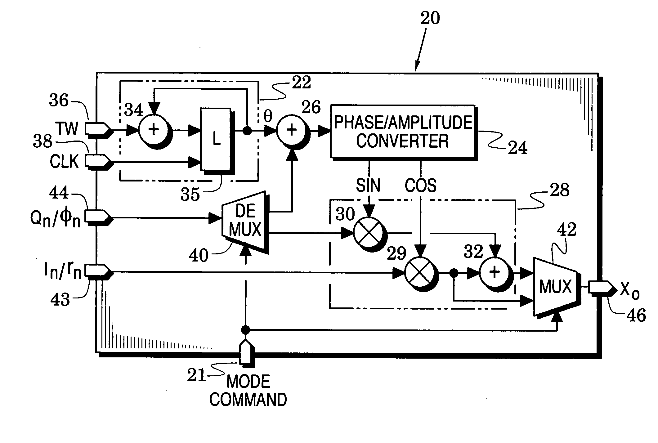
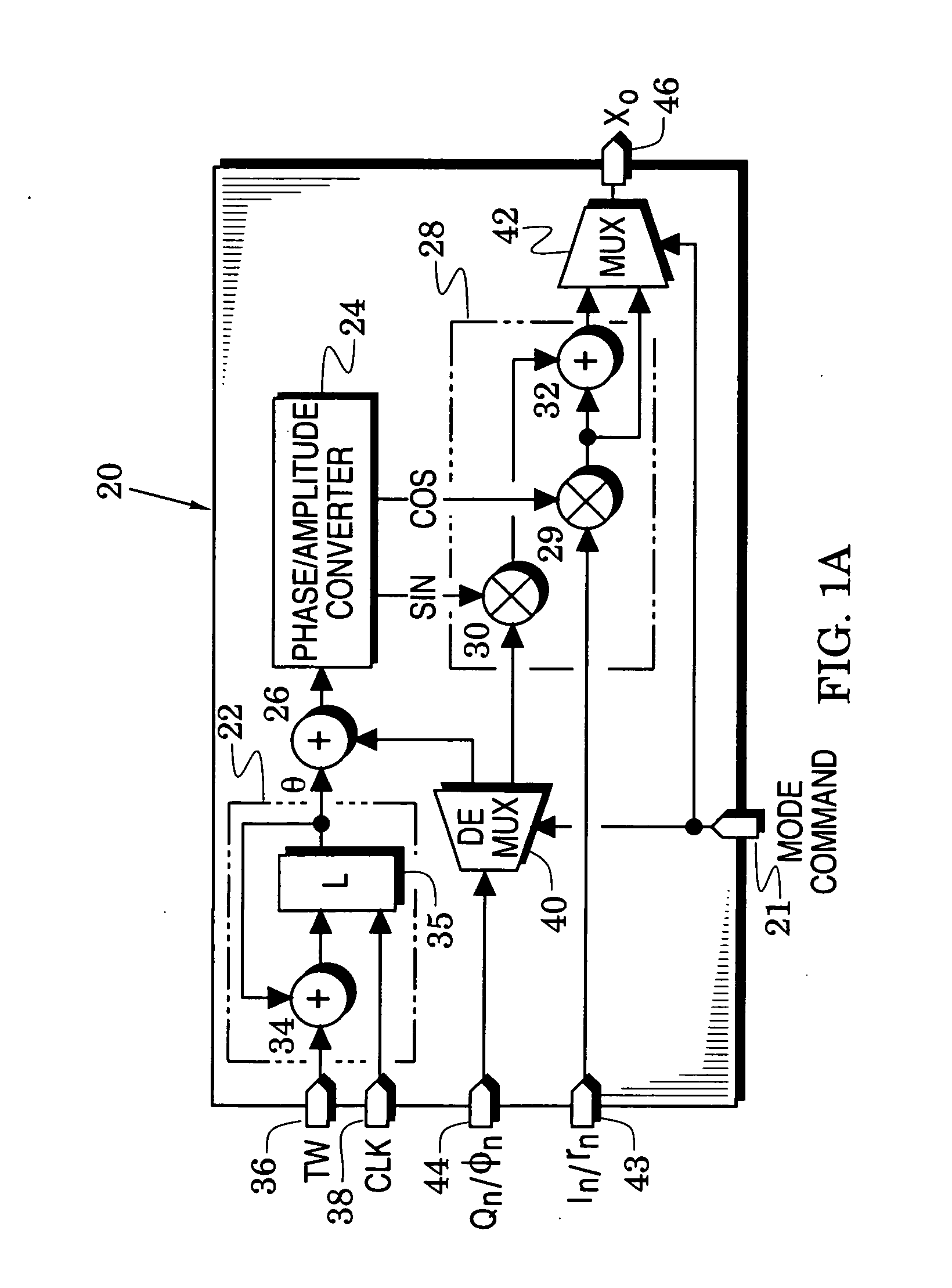
[0017] In an important feature of the embodiment 20, the quadrature modulator 28 is coupled between an input demultiplexer (DEMUX) 40 and an output multiplexer (MUX) 42 that both respond to the mode command at the mode port 21. The demultiplexer has an input coupled to the symbol input port 44 and has two outputs coupled respectively to the first summer 26 and the second multiplier 30. The multiplexer 42 has two inputs respectively coupled to the first multiplier 29 and the second summer 32 and has an output coupled to a modulator output port 46.
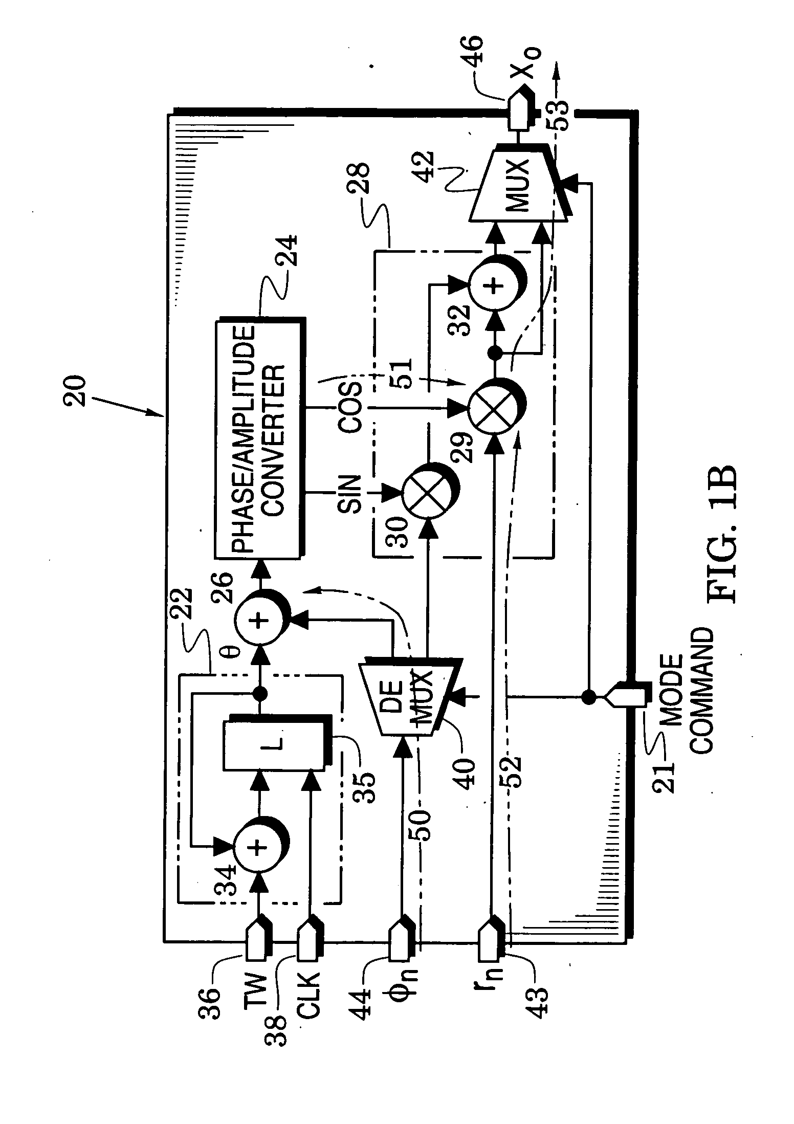
[0018] Polar-modulated operation of the modulator embodiment 20 is illustrated in FIG. 1B which includes the structures of FIG. 1A with like elements indicated by like reference numbers. In this figure, a first state of the mode command has commanded the demultiplexer 40 to route input phase symbols φn (received at symbol input port 44) along a signal path 50 to the first summer 26 where the phase symbols φn are added to thereby alter the ph...
embodiment 60
[0028] Finally, the embodiment 60 also provides first and second digital-to-analog converters (DACs) 78 and 79 which respectively convert the output sequences Xo and Yo into first and second analog signals Xf and Yf.
[0029]FIG. 2A illustrates another universal signal modulator embodiment 90 which includes the structures of the signal modulator 60 of FIG. 1D with like elements indicated by like reference numbers. In FIG. 2A, however, the multiplexers 63 and 64 of FIG. 1D have been replaced by the ports 43 and 44 of FIG. 1A and the physical location of quadrature modulators 28 and 68 have been interchanged to simplify the flow of signals through the figure.
[0030] The modulator 90 replaces the phase-to-amplitude converter 24 of FIG. 1A with a coarse phase-to-amplitude converter 93 and inserts an octant phase generator 92 between the converter 93 and the first summer 26. The sine and cosine sequences of the first and second quadrature modulators 28 and 68 are provided by the coarse phas...
embodiment 90
[0042] Polar-modulated operation of the modulator embodiment 90 is further illustrated in FIG. 2B which includes the structures of FIG. 2A with like elements indicated by like reference numbers. In this figure, the phase symbols φn are processed along a signal path 112 that passes through the second demultiplexer 40 and the first summer 26. The amplitude symbols rn are processed along signal paths 114 that pass through the first demultiplexer 100 and the first and fourth multipliers 29 and 70.
[0043] Quadrature-modulated operation of the modulator embodiment 90 is further illustrated in FIG. 2C which includes the structures of FIG. 2A with like elements indicated by like reference numbers. In this figure, the first quadrature symbols In are processed along a signal path 116 that passes through the second demultiplexer 100, the interchanger 102 and the first quadrature modulator 28. The second quadrature symbols Qn are processed along a signal path 118 that passes through the first de...
PUM
 Abstract
Description
Claims
Application Information
 - R&D
- Intellectual Property
- Life Sciences
- Materials
- Tech Scout
- Unparalleled Data Quality
- Higher Quality Content
- 60% Fewer Hallucinations
Browse by: Latest US Patents, China's latest patents, Technical Efficacy Thesaurus, Application Domain, Technology Topic, Popular Technical Reports.
© 2025 PatSnap. All rights reserved.Legal|Privacy policy|Modern Slavery Act Transparency Statement|Sitemap|About US| Contact US: help@patsnap.com


