System for attaching accessories to a shelf

Inactive Publication Date: 2006-11-23
HL DISPLAY
View PDF15 Cites 138 Cited by
  • Summary
  • Abstract
  • Description
  • Claims
  • Application Information

AI Technical Summary

Benefits of technology

[0014] Another object is to produce such a system which allows individual accessories to be fastened and / or detached from the shelf even when other accessories disposed on the shelf are fixed in their respective positions.
[0017] The elastic member thus enables individual accessories to be fastened to and / or detached from the shelf without the release of other already fixed accessories. This substantially facilitates the work on reorganizing an already ordered shelf, since there is no risk of the accessories which are correctly placed being displaced, toppling over or coming loose. Moreover, the elastic member is able to absorb measurement deviations of the holding member and of the feet of the accessories without the risk of any accessory being held with a lower holding force.
[0018] Further objects and advantages of the system according to the invention derive from the dependent patent claims 2-14. For example, the holding member can be configured so as, in its holding position, to prevent displacement of the accessories along the shelf. This effectively stops the accessories from being mistakenly dislodged from their intended positions, for example by passing customer trolleys banging against the shelf. Depending on the application of the system, the elastic member can either be disposed on the holding member or on the accessory foot. According to one particular embodiment, the holding member is constituted by an elongated leaf spring, which constitutes the elastic member. Further, the foot and the channel element of the shelf divider can be configured with interacting engagement members, which increase the stability of the accessory and which additionally prevent the accessory from toppling over when it is fixed to the shelf. The interacting engagement members can be configured as a projecting bead arranged on the foot or the channel element and as a corresponding recess in the other part. A particular advantage is herein achieved if the projecting bead is disposed on the channel element and the recess on the accessory foot. Such an arrangement namely prevents improper accessories, which do not have the recess, from being able to be introduced into the channel element and used together with the system. According to one embodiment, the channel element can be configured as an elongated profile element. This allows cheap and simple production of the channel element by extrusion. At the same time, such a configuration of the channel element allows simple attachment of the channel element to the front edge of the shelf, for example by screwing or by means of double-sided adhesive tape, the system being able to be applied to and used in a host of different pre-existing shelves without special adaptation thereof. Alternatively, the channel element can be fastened in a groove or a recess disposed in the shelf. Although this requires the shelf to be specially configured with such a groove, it simultaneously implies a better integration of the system with the shelf and a more aesthetically pleasing configuration.

Problems solved by technology

The arrangement according to U.S. Pat. No. 5,657,702 has also, however, a serious drawback, which makes it especially difficult to reorganize shelves which have already been put in order.
Since all the shelf dividers are locked to the shelf when the locking bar is in its locking position, it is not possible to move, remove or attach an individual shelf divider without first freeing all the dividers disposed on the shelf.
Those dividers which are not to be moved are also at risk of being displaced from their respective positions, of falling over or of coming completely loose from the shelf.
Particularly in the reorganization of ordered shelves on which goods are already set up, this is a serious problem.
When a shelf divider is to be moved, removed, or attached, there is a high risk of an adjoining one being touched or displaced.
This goods displacement is easily transmitted via tightly packed adjacent goods and can lead to a number of more distant shelf dividers toppling over or being displaced from their intended positions.
This is not only a time-consuming and costly exercise per se, but also leads to a reluctance to reorganize already ordered shelves to accommodate new goods and packagings.
Consequently, the limited shelf space is not optimally utilized, whilst, at the same time, ill-organized shelves give an unaesthetic impression and adversely affect the tendency of the store customers to select goods from-these shelves.
A further problem with the known arrangement described above is that the holding of one or more shelf dividers cannot be ensured if the thickness of the flanges of any of the shelf dividers differs from the nominal production thickness.

Method used


Image

  • System for attaching accessories to a shelf
  • System for attaching accessories to a shelf
  • System for attaching accessories to a shelf

Examples


Embodiment Construction

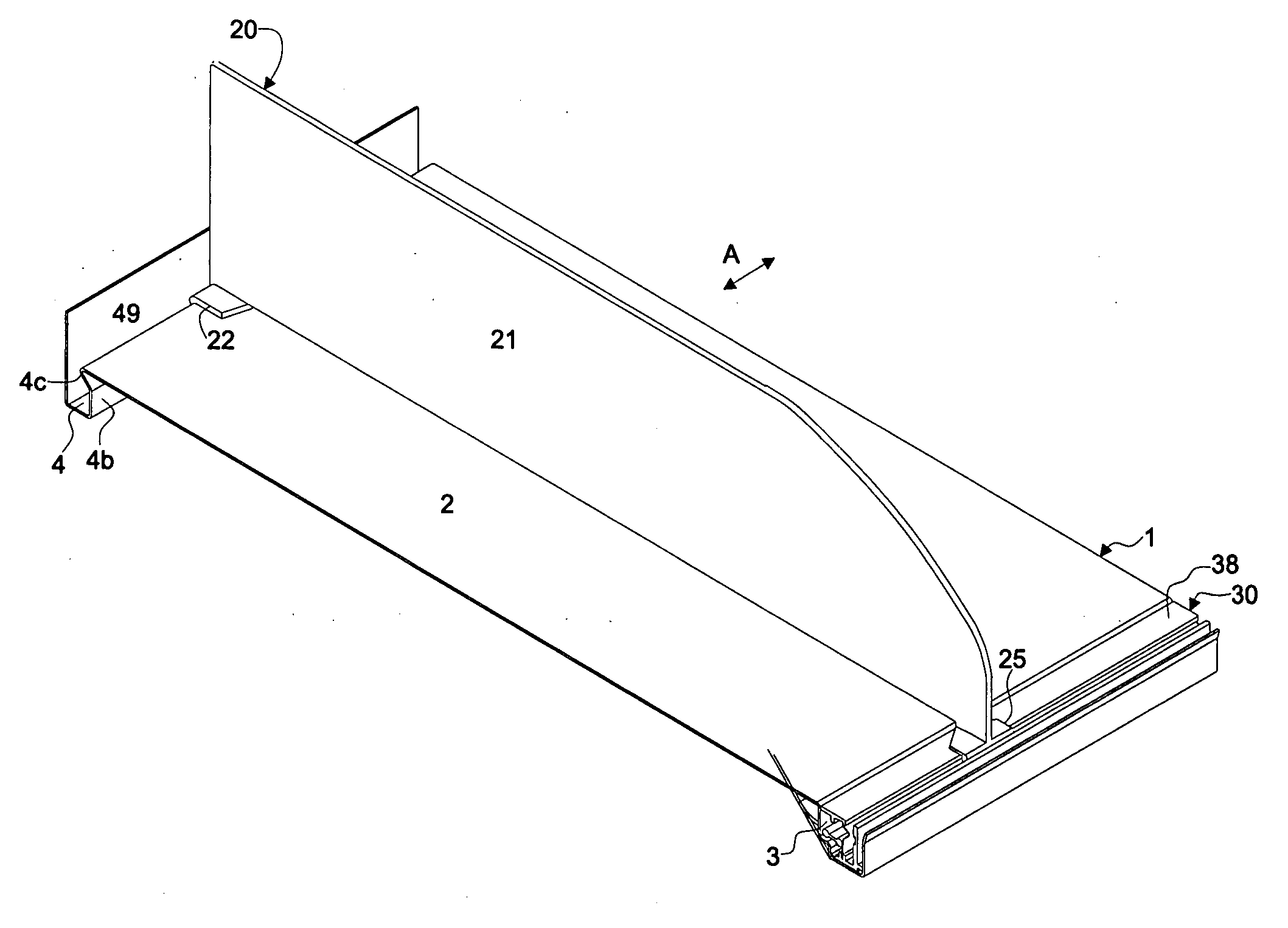
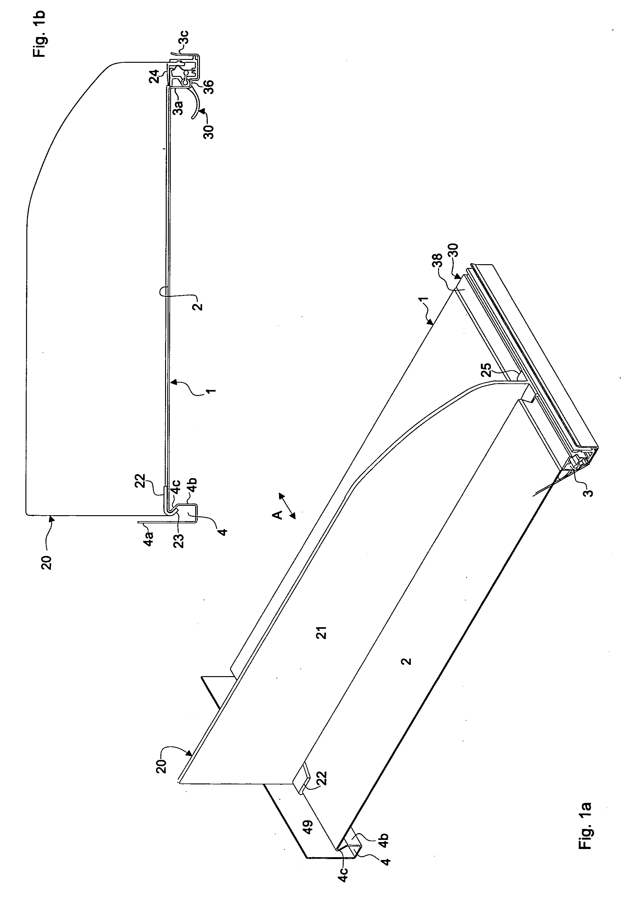
[0029]FIGS. 1a and 1b show a shelf 1 provided with a system according to the invention. In the figures, only a section of the shelf 1 is shown, but it will be appreciated that the shelf extends substantially further in its longitudinal direction, which, in FIG. 1a, is indicated by the double arrow A. The shelf 1 has a horizontal shelf plane 2 and a front 3 and a rear 4 upwardly open groove, which grooves 3, 4 extend parallel with the longitudinal direction and are depressed in relation to the shelf plane 2. The cross section of the front groove 3 is in the general shape of a U, the rear vertical wall 3a of the groove 3 having a shoulder 3b, so that the upper part of the groove 3 is wider than its lower part. The cross section of the rear groove 4 is also in the general shape of a U, the rear wall 4a of the groove 4 being higher than its front wall 4b, which front wall 4b has a longitudinal bulge 4c projecting rearward into the groove.

[0030]FIGS. 1a and 1b also show a system accordi...


PUM


Abstract

A system for fixing accessories, such as shelf dividers, feed devices, holders for information carriers etc. to a shelf, to which self a number of accessories may be fixed detachably in various different positions along the length of the shelf. The system includes at least one accessory provided with a foot, and a clamping device, which includes a channel element, extending in parallel with the longitudinal direction of the shelf and presenting an open longitudinal side for forming an open channel, a actuable holding member, extending along the channel element for holding at least one foot in the channel and a control member for transferring the holding member between a holding position, in which the foot is held in a fixation position in the channel and a release position at which the foot is freed.

Description

FIELD OF THE INVENTION [0001] The present invention relates to a system for fixing accessories, such as shelf dividers, feed devices, holders for information carriers, etc. to a shelf, to which shelf a number of accessories can be fixed detachably in various positions along the length of the shelf. The system comprises at least one accessory having a foot and a clamping device, which latter comprises a channel element extending parallel with the longitudinal direction of the shelf and having an open longitudinal side for forming an open channel, an actuable holding member, extending along the channel element, for holding at least one foot in the channel, and a control member for transferring the holding member between a holding position, in which the foot is held in a fixation position in the channel, and a release position, in which the foot is freed. [0002] The invention also relates to a clamping device and an accessory for such a system, a shelf comprising such a system and a sh...

Claims


Application Information

Patent Timeline
IPC IPC(8): A47B57/00A47F5/00G09F3/20
CPCA47F5/005G09F3/204A47F5/0068
Inventor JOSEFSSON, BORJEAHLUND, BENGTCUHNA, PEDROHILDINGSSON, MICHAELLINDSTROM, JAN
Owner HL DISPLAY
Why Eureka
Try Eureka