
Surgical drains

a surgical and drain technology, applied in the field of high-performance surgical drains, can solve the problems of significant potential for clogging, and achieve the effect of further reducing the likelihood of clogging the drain

Inactive Publication Date: 2006-11-16
JS VASCULAR
View PDF7 Cites 8 Cited by
  • Summary
  • Abstract
  • Description
  • Claims
  • Application Information

AI Technical Summary

Benefits of technology

"The present invention is an improved surgical drain for draining bodily materials from wounds. The drain has a longer, more open area per drain surface area than known drains, making it more effective. The drain has a single, continuous elongate member with a large interior lumen that can receive bodily materials and a larger external lumen for connecting to an outflow tube. The drain is made of highly pliant, biocompatible plastic elastomeric silicone. The drain has large and small cross-sectional openings that prevent tissue growth and are easier to keep open. The drain is strong enough to withstand pulls without fracturing or separating. The large openings provide adequate drainage of large particles of bodily materials. The external section of the drain has a larger lumen to connect to an outflow tube that prevents clogging."

Problems solved by technology

Such procedures often have small entrance incisions and maximal undermining, which have a significant potential to form clots.

Method used


Image

  • Surgical drains
  • Surgical drains
  • Surgical drains

Examples


Embodiment Construction

[0038] Reference shall now be made to the accompanying figures, wherein the purpose is to describe preferred embodiments of the invention and not to limit same. A drain according to the invention preferably includes a single, continuous, elongate, flexible member, and any suitable material, size, thickness or shape may be utilized.

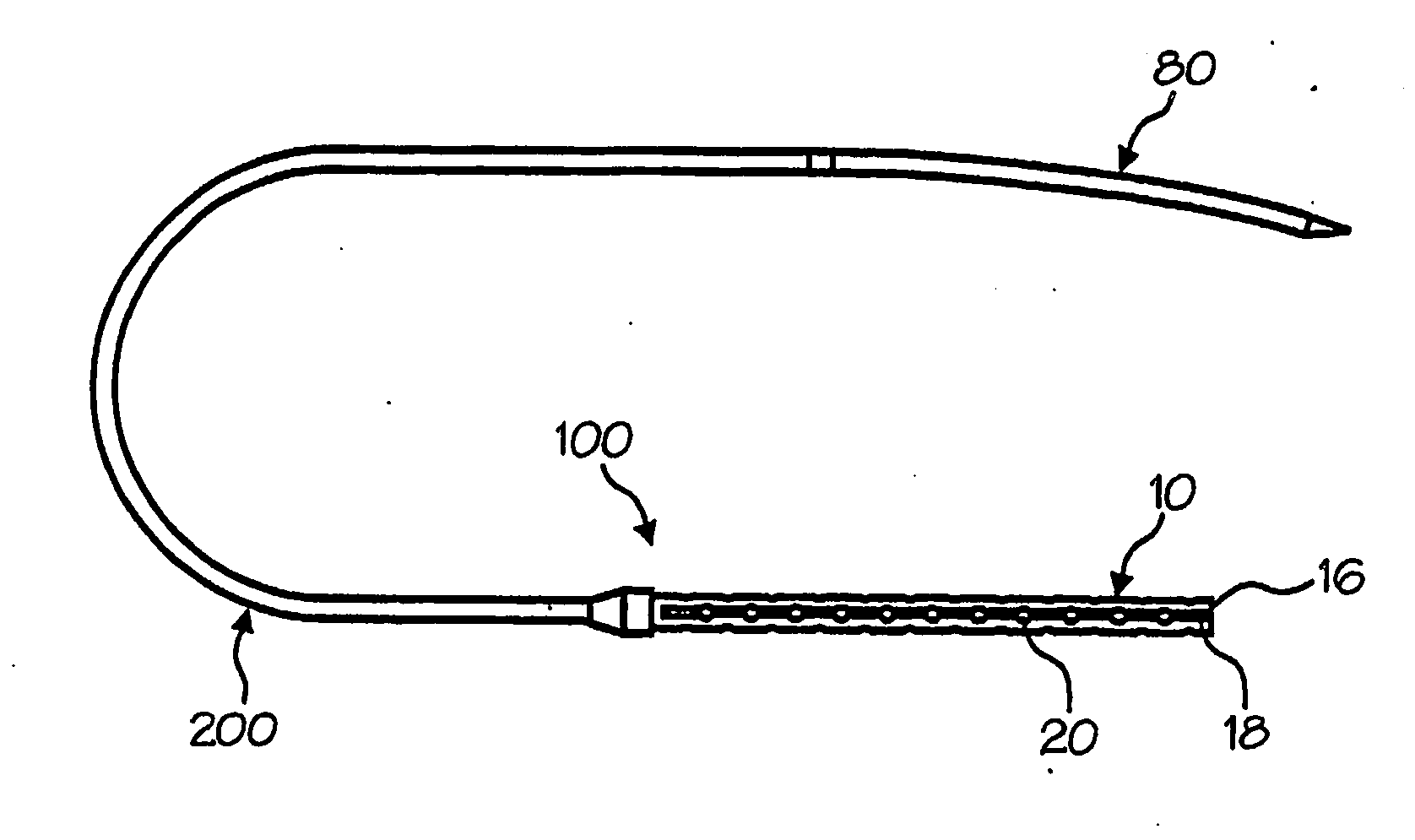
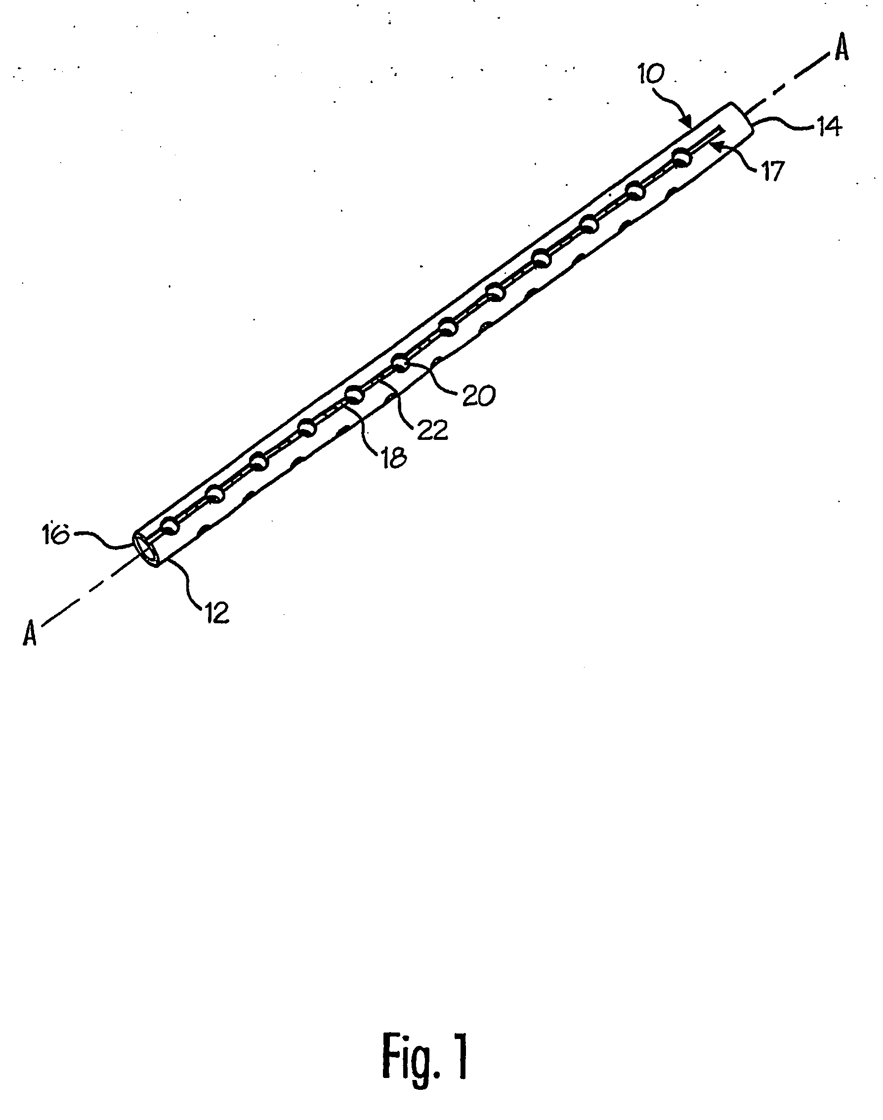
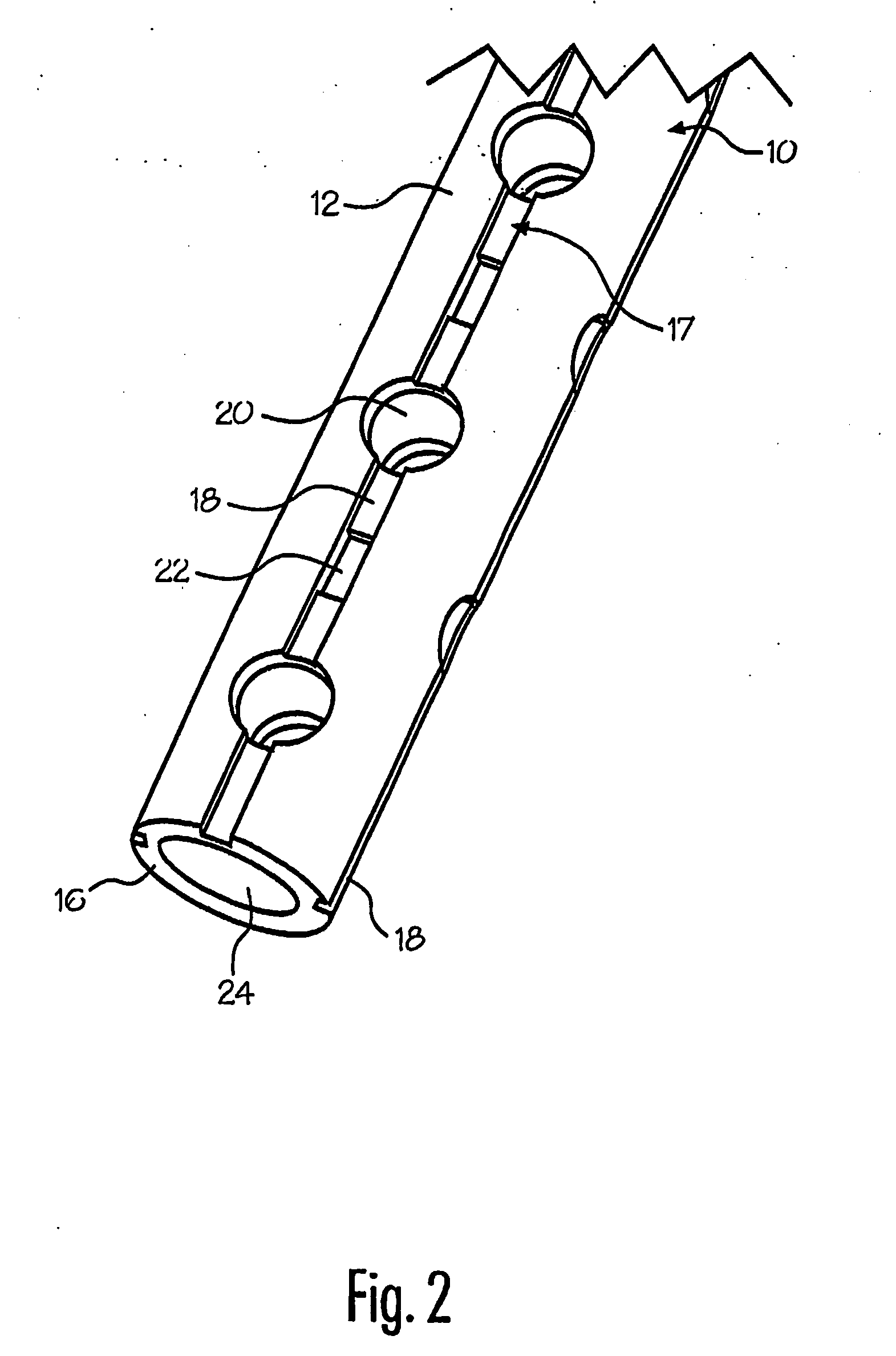
[0039] As shown in FIGS. 1-8, a drain 10 and optional drain system 100 utilizing the drain are illustrated. Drain 10 is generally an elongated, tubular member and is preferably injection molded of a flexible plastic or rubber matter, such as silicone rubber. Any suitable method of manufacture or type of material may be used, however. Drain 10 has an exterior surface 12, a first end 14, a second end 16 and an internal lumen 24, preferably having a circular cross-section and a diameter of about 6 mm, extending therethrough. The purpose of lumen 24 is to receive bodily material collected from the outer openings in drain 10 and transport the bodily material o...


PUM


Abstract

Disclosed are surgical drains for use in surgical wounds. The drains are placed in the wound in the body and draw in unwanted bodily material. The drains can be of any shape, but preferably have a generally circular cross section or include a generally flat top surface, a generally flat bottom-surface and two sides connecting the top surface and bottom surface. The drain has an outer surface, two ends, a length and an interior lumen that may extend substantially along the length. At least one row of openings is formed in the outer surface along the longitudinal axis. The openings in a single row may comprise large cross-sectional openings alternating with small cross-sectional openings. If a plurality of rows are utilized, the small cross-sectional openings may not be included. It is preferred that the large cross-sectional openings in one row be offset, or staggered, from the large cross-sectional openings in a neighboring row. The flat drain may include large openings on one or more of the flat surfaces and smaller openings on the sides. It is preferred, but not required, that at least some of the openings be formed in the base of a channel formed in the outer surface of the drain.

Description

RELATED APPLICATIONS [0001] This application claims priority to U.S. Provisional Application Ser. No. 60 / 476,663, filed Jun. 5, 2003, and to U.S. Provisional Application Ser. No. 60 / 539,158, filed Jan. 26, 2004, the disclosure of which is hereby incorporated by reference.FIELD OF THE INVENTION [0002] This invention relates to medical devices and, more specifically, to high-performance surgical drains providing improved drainage. BACKGROUND OF THE INVENTION [0003] Modern surgery increasingly attempts to minimize the length and trauma of surgery, and surgical incisions. Today, incisions can be quite small, but despite the small entry and exit incisions, significant surgery, resulting in wounds to internal body tissue, continues to be done inside the human body either percutaneously, laproscopically or in open-cut surgeries. As a consequence, considerable undermining may occur. Current surgical drains are not ideally suited to such circumstances. Most current surgical drains are short ...

Claims


Application Information

Patent Timeline
Patent Type & Authority Applications(United States)
IPC IPC(8): A61M1/00A61B17/00A61M27/00
CPCA61B17/00008A61M27/00A61M1/0088A61M1/0011A61M1/90A61M1/68
Inventor OPIE, JOHN C.JOYCE, STEPHEN J.IZDEBSKI, THOMAS
Owner JS VASCULAR
Learn More