
Apparatus for removably securing storage components in an enclosure

a technology for removable securing and storage components, which is applied in the direction of electrical apparatus casings/cabinets/drawers, instruments, cabinets, etc., can solve the problems of data loss, inability to tolerate, and associated scsi and fibre channel storage components are four to six times more expensive than the traditional ide (integrated device electronics) storage components

Active Publication Date: 2006-11-09
LATTICE SEMICON CORP
View PDF13 Cites 114 Cited by
  • Summary
  • Abstract
  • Description
  • Claims
  • Application Information

AI Technical Summary

Benefits of technology

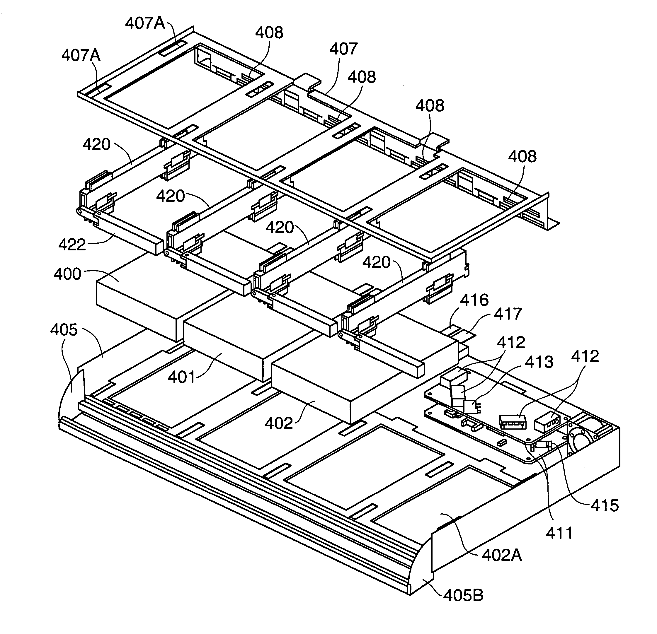
[0021] In a class of embodiments, the invention is an assembly in which SATA disk drives (or other storage components) can be removably secured, with at least one connector of each storage component accessible for coupling to (and decoupling from) a complementary connector. In accordance with typical embodiments of the invention, bare storage components (e.g. inexpensive SATA disk drives or other inexpensive storage components) can be secured in an enclosure without the need first to mount any of them in or to an individual carrier, and such that they can be conveniently removed from the enclosure and replaced (e.g., when they fail). The expression that a storage component is a “bare” storage component herein denotes that the storage component is not mounted in or to a tray, an individual disk carrier, or other carrier or support structure. In typical embodiments, one or more bare storage components (e.g., bare SATA disk drives) are removably secured in an enclosure.
[0026] In other embodiments, a storage component that is to be (or has been) fixedly secured in an enclosure in accordance with the invention is coupled to a non-floating connector of a cable. In some such embodiments, a wall of the enclosure defines an opening into which the non-floating connector is inserted, and this wall has a floating section having limited freedom to move relative to the storage component and the rest of the enclosure. When the non-floating connector has been inserted into the opening of the floating section of the wall, the non-floating connector and floating section of the wall can be moved together (as a unit) relative to the storage component to allow the non-floating connector to be coupled easily to a complementary connector of a storage component within the enclosure.

Problems solved by technology

Due to the importance of the data, data loss (e.g., due to a hard disk drive failure) cannot be tolerated.
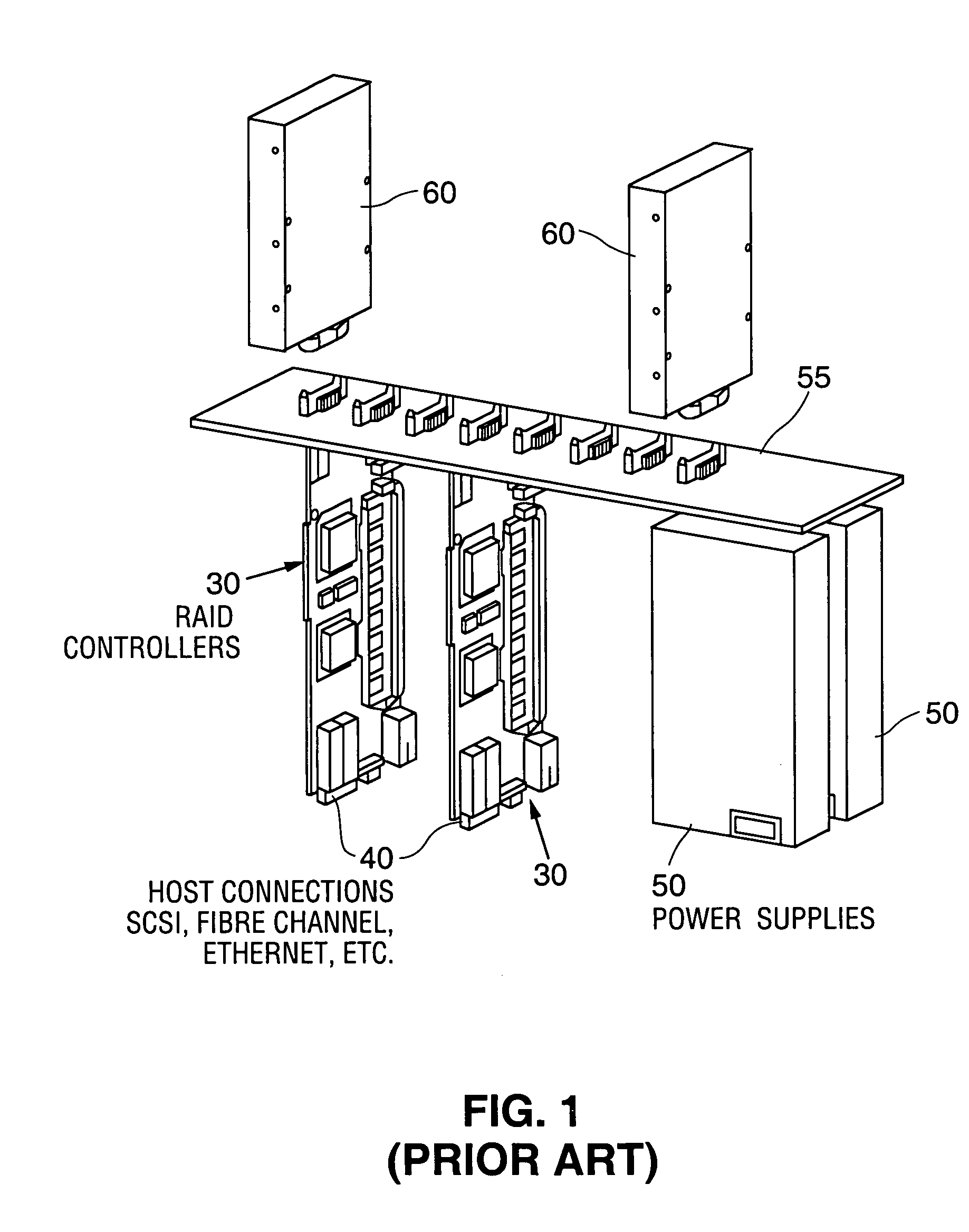
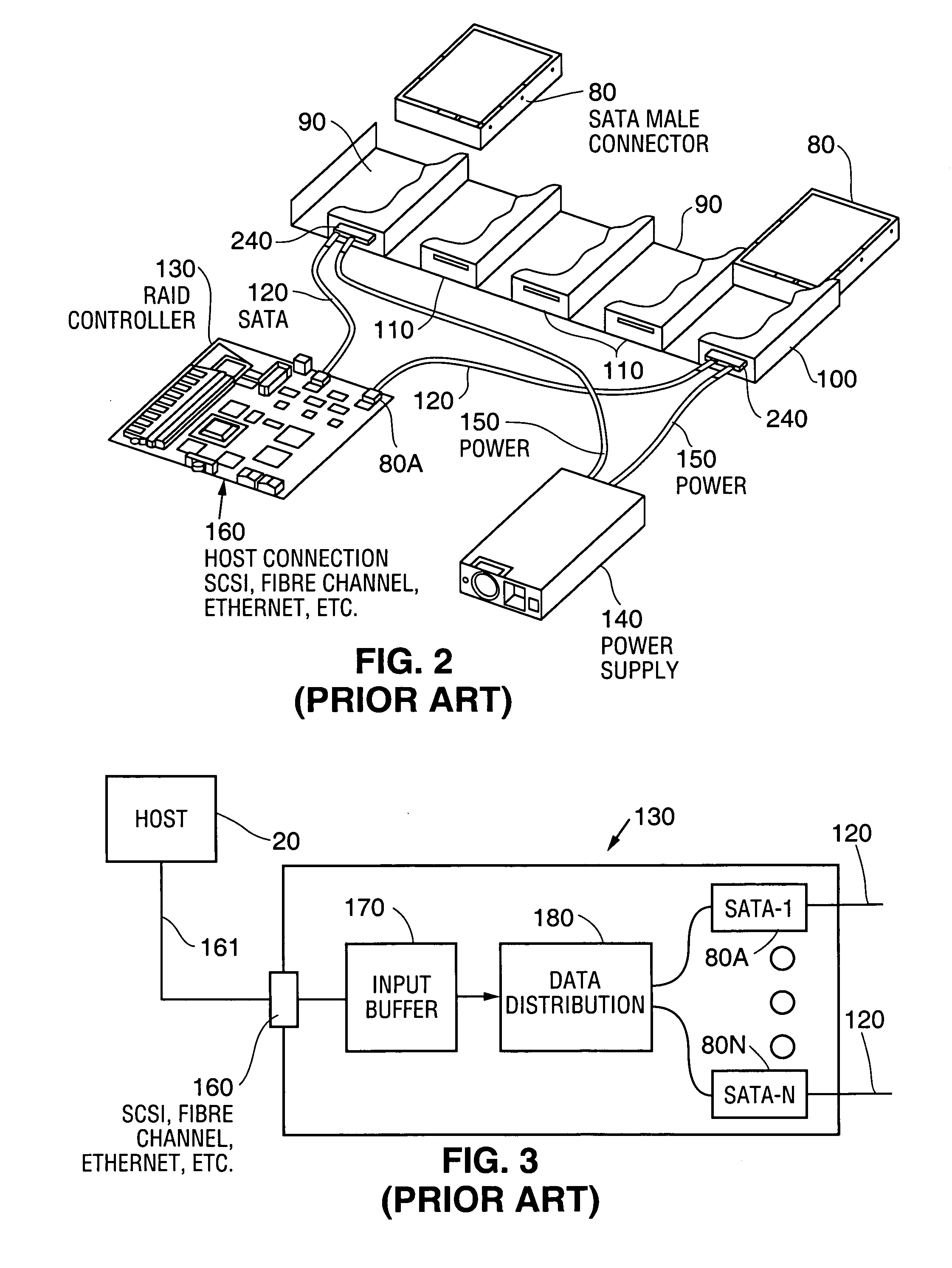
While the SCSI and fibre channel standards support multi-storage system environments, the associated SCSI and fibre channel storage components are four to six times more expensive than the traditional IDE (integrated device electronics) storage components that are used in most PC's.
The IDE standard only supports the connection of two IDE storage components, however, and is therefore not ideal for use in a multi-storage component environment.
However, the SATA standard requires tight impedance control for on board signal routes and as a result SATA storage components cannot simply be plugged into a circuit board substrate due to potential distortion.
Among the disadvantages and limitations of conventional systems that include a backplane (e.g., backplane 55 of FIG. 1) for connecting storage devices to other elements are that a backplane typically is undesirably bulky, and since component location is fixed due to the use of plug-in boards with a backplane, system design is constrained.

Method used


Image

  • Apparatus for removably securing storage components in an enclosure
  • Apparatus for removably securing storage components in an enclosure
  • Apparatus for removably securing storage components in an enclosure

Examples


Embodiment Construction

[0043] With reference to FIGS. 4, 5, and 6, we describe a SATA cable (190) that can be coupled to a typical SATA storage component that has been (or is to be) secured in an enclosure in accordance with a class of embodiments of the present invention. To manufacture SATA cable 190, flanges 210 and 220 are attached in the positions shown to a conventional SATA cable comprising all other elements (all elements other than flanges 210 and 220) shown in FIGS. 4-6. Restraining flange 220 is sized and shaped so that it can pass through opening 110 of chassis 100 (if tilted sufficiently), so that flanges 220 and 210 (respectively) rest adjacent to the interior and exterior sides of the wall defining opening 110, and so that cable 190 cannot easily be tilted to allow flange 220 to pass back out through opening 110. The opening 110 is sized to have smaller height than do flanges 210 and 220 but greater height than the rest of cable 190. As a result, the flanges 210 and 220 loosely hold connect...


PUM


Abstract

In some embodiments, an assembly in which storage components (e.g., at least two bare SATA disk drives) can be removably secured. The assembly can secure bare storage components in an enclosure without the need first to mount any of them in or to a carrier, and such that they can be conveniently removed from the enclosure and replaced (e.g., when they fail). Some embodiments include a flexible assembly for each storage component, including at least one flexible element and at least one swaged cam for each flexible element. The flexible assembly has two states: a locking state in which each cam deforms a flexible element into a locking position; and an unlocking state in which each cam and each flexible element have relative positions that allow the storage component to move past each flexible element. Other embodiments include a spring-biased assembly for each storage component, having a locking state in which at least one spring element (e.g., a metal flange) exerts spring force on the storage component to maintain it in a locked position; and an unlocking state in which each spring element has relaxed away from the storage component to allow the storage element to move out of the locked position.

Description

FIELD OF THE INVENTION [0001] The present invention relates to apparatus for removably securing one or more storage devices in an enclosure with at least one connector of each storage device accessible for coupling to (and decoupling from) a complementary connector. In some embodiments, the invention relates to apparatus for removably securing two or more bare SATA (serial ATA) storage devices in an enclosure, with a SATA connector of the storage device accessible for coupling to (and decoupling from) a complementary connector of a SATA cable. BACKGROUND OF THE INVENTION [0002] The following definitions apply throughout the specification, including in the claims: [0003]“SATA standard” denotes the standard known as Serial ATA, Revision 1.0, adopted on Aug. 29, 2001, by the Serial ATA Working Group, for communication between a host and one or more storage devices over one or more serial links; [0004]“SATA system” denotes a system including elements (sometimes referred to as “SATA comp...

Claims


Application Information

Patent Timeline
IPC IPC(8): G06F1/16
CPCG06F1/187G06F1/00G06F1/1656G06F1/1675G06F2200/163
Inventor BLAALID, JEFFREY SCOTTYOUNG, JAMES PAT
Owner LATTICE SEMICON CORP
Learn More