Multi-axis prosthetic ankle

a prosthetic ankle and multi-axis technology, applied in the field of prosthetic devices, can solve the problems of choppy, unnatural and uncomfortable gait, and inability to optimally control multi-axis motion of most prosthetic ankles currently on the market, and achieve the effects of limiting the range of motion of the ankle, enhancing the movement of the lower leg connection component, and limiting the movement of the ankl

Inactive Publication Date: 2006-11-02
WILLOWWOOD GLOBAL LLC
View PDF35 Cites 23 Cited by
  • Summary
  • Abstract
  • Description
  • Claims
  • Application Information

AI Technical Summary

Benefits of technology

[0009] In this particular embodiment of the present invention, the mechanical device comprises a cavity in the prosthetic foot connection component that is substantially defined by a plurality of vertically extending walls, and a generally hook-shaped projection extending from the lower leg connection component. The hook-shaped projection of the lower leg connection component floatingly resides within the cavity in the prosthetic foot connection component. Contact between a portion of the hook-shaped projection and a rigid wall of the prosthetic foot connection component can be utilized to restrict the range of motion of the lower leg connection component. Other points of contact between the lower leg connection component and the prosthetic foot connection component may be similarly utilized.
[0010] By terms such as “interlockingly float” and “floatingly resides” it is meant that the first and second elements are suspended in the elastomeric material in close relation to one another, but are retained in position by the intermediary elastomeric material, not by contact with one another. Since the deformation of the elastic material permits multi-axis relative movement of the bottom component and the lower leg connection component, including translational movement, the ankle joint of the invention can simulate natural ankle motion by providing plantar flexion, dorsi flexion, inversion, eversion, translation and internal / external rotational movement. Such motion is optimally controlled by the multi-axis deformation of the elastic material, without sacrificing the energy return of the prosthetic foot. Further, since the components of the mechanical device are bonded to, and encased by, the elastomeric material, the ankle has the ability to absorb and damp both rotational and linear impacts.
[0011] As force is applied to either of these ankles, the ankle moves in rotation and translation with a fluid motion by deforming the elastomeric medium. According to a further feature of the invention, at least one mechanical stop may also be positioned on / in either of these multi-axis ankle embodiments to prevent the relative angular movement of the ankles from deforming the elastomeric material beyond the elastic limit thereof. Since the deformation of the elastomeric material in both multi-axis ankle embodiments is thus always kept within the elastic limit, any tendency toward breakdown of the elastomeric material is further reduced.
[0013] In this particular embodiment of the present invention, the mechanical connection may comprise a pin that resides in an aperture passing through both an upwardly-extending portion of the prosthetic foot connection component and a downwardly-extending projection of the lower leg connection component. A bearing, such as a spherical bearing, may be located in the downwardly-extending projection of the lower leg connection component to receive the pin and enhance movement of the lower leg connection component. The upwardly-extending portion of the prosthetic foot connection component may comprise two legs, such that the downwardly-extending projection of the lower leg connection component may reside therebetween. A dorsi-flexion stop may be located in the prosthetic foot connection component so as to contact a portion of the downwardly-extending projection of the lower leg connection component and limit the range of motion thereof. Alternatively, a dorsi-flexion stop may be located in a projection of the lower leg connection component and adapted to contact a portion of the prosthetic foot connection component in order to limit ankle movement.
[0014] As force is applied to this embodiment of the multi-axis ankle, the ankle moves in rotation with a fluid motion by pivoting about the pin and simultaneously deforming the elastomeric material. The ankle is also able to move in translation via the inherent tilting ability of the spherical bearing. Since deformation of the elastomeric material in this embodiment is always kept within the elastic limit by means of the dorsi-flexion stop and the limited translational movement of the downwardly-extending projection of the lower leg connection component, breakdown of the elastomeric material is minimized.

Problems solved by technology

Most prosthetic ankles currently on the market, however, do not provide optimally controlled multi-axis motion.
Often the prosthetic ankle has such a low stiffness that it effectively reduces any functional capabilities of the attached prosthetic foot, resulting in a choppy, unnatural and uncomfortable gait.
However, conventional prosthetic ankle joints that provide multi-axis motion tend to require extensive maintenance including the replacement of parts in order to function properly.
This surface-to-surface sliding motion is the primary cause of material breakdown.

Method used


Image

  • Multi-axis prosthetic ankle
  • Multi-axis prosthetic ankle
  • Multi-axis prosthetic ankle

Examples


Embodiment Construction

)

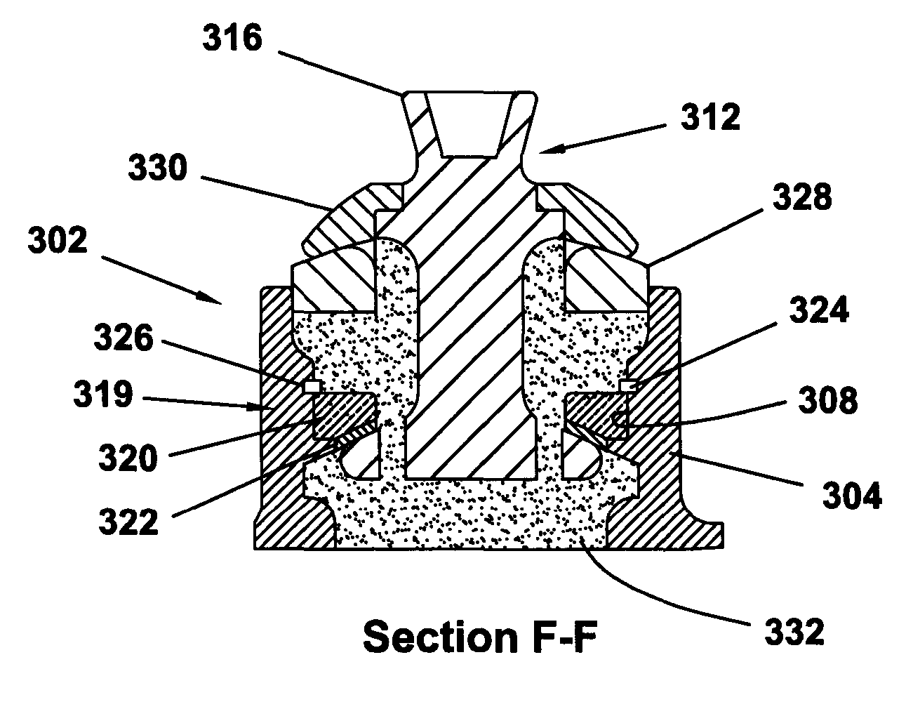
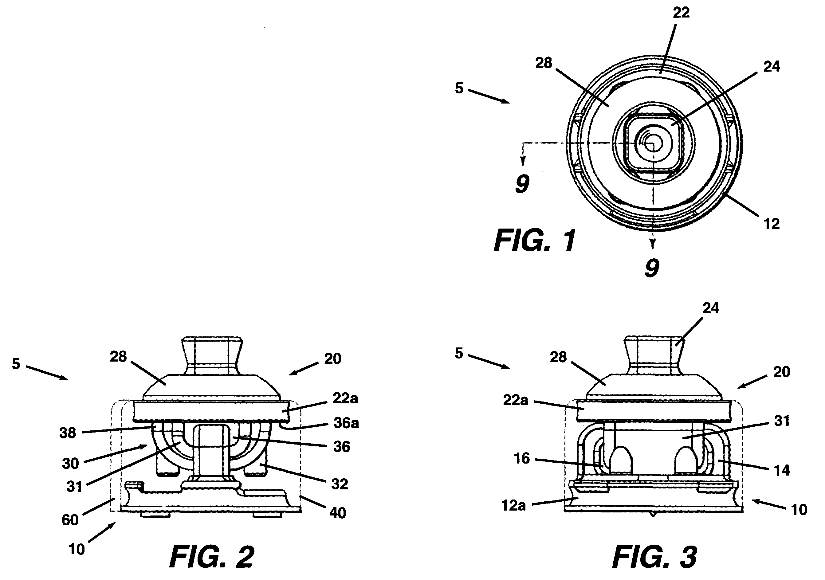
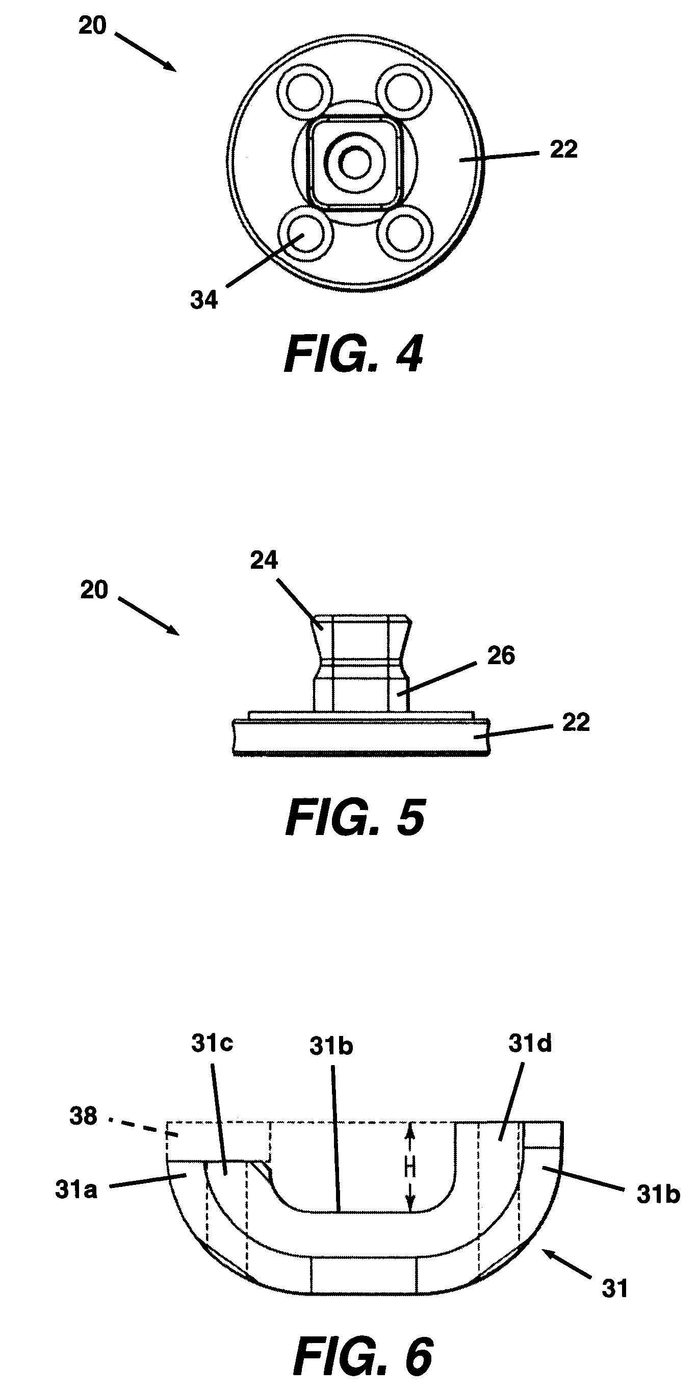
[0067] A first exemplary embodiment of a multi-axis prosthetic ankle according to the present invention can be observed by reference to FIGS. 1-9. As can be seen, particularly with respect to FIGS. 2-3, for clarity of illustration the elastomeric casing is shown in phantom lines, thereby revealing the encased components of the mechanical device (rigid mechanical means). In this particular embodiment, the main components of the multi-axis prosthetic ankle 5 are the bottom component 10, the lower leg connection component 20, the mechanical device 30 (rigid mechanical means), and the elastomeric casing 40, which is bonded to the bottom component and the lower leg connection component and floatingly encases the elements of the mechanical device.

[0068] Referring more particularly to FIGS. 7 and 8, the bottom component 10 comprises a generally circular disk like base 12, and a first “U” shaped bracket 14 (first rigid element) projecting perpendicularly upwardly from the base. The first ...


PUM


Abstract

A multi-axis prosthetic ankle for connection of a prosthetic lower leg to a prosthetic foot. A substantially hollow prosthetic foot connection component includes a receiving cavity for receiving a portion of a lower leg connection component. A retainer or retainer assembly is preferably installed into the receiving cavity to help retain the lower leg connection component therein. Once the necessary components are in place, the remainder of the receiving cavity is substantially filled with an elastomeric material. An external bearing may reside atop the elastomeric material and act in conjunction with the elastomeric material to control ankle flexion.

Description

[0001] This application is a continuation-in-part of U.S. patent application Ser. No. 10 / 770,833, filed on Feb. 3, 2004, which is a continuation-in-part of U.S. patent application Ser. No. 09 / 893,887, filed on Jun. 29, 2001, now U.S. Pat. No. 6,699,295, issued Mar. 2, 2004.BACKGROUND OF THE INVENTION [0002] The present invention relates generally to prosthetic devices, and more particularly to multi-axis prosthetic ankles. [0003] A prosthetic ankle is a component which connects a prosthetic foot with a prosthetic lower leg. For smooth walking, especially, across uneven ground, it is important for the ankle to be designed for a full range of foot motion with respect to the lower leg prosthesis. One embodiment of such an ankle is described in U.S. patent application Ser. No. 09 / 893,887, which is hereby incorporated by reference herein. Most prosthetic ankles currently on the market, however, do not provide optimally controlled multi-axis motion. Often the prosthetic ankle has such a l...

Claims


Application Information

Patent Timeline
Patent Type & Authority Applications(United States)
IPC IPC(8): A61F2/66A61F2/62A61F2/00A61F2/50A61F2/76
CPCA61F2/5044A61F2310/00047A61F2/76A61F2002/30131A61F2002/30359A61F2002/30365A61F2002/30434A61F2002/30443A61F2002/305A61F2002/3051A61F2002/5003A61F2002/5007A61F2002/5043A61F2220/0025A61F2220/0033A61F2220/0041A61F2230/0013A61F2310/00017A61F2310/00023A61F2/6607A61F2002/30433A61F2002/30507
Inventor DODDROE, JEFFREY L.COLVIN, JAMES M.ARBOGAST, ROBERT E.NOLT, LONNIE L.
Owner WILLOWWOOD GLOBAL LLC
Why Eureka
Try Eureka