
Method and apparatus for non-disruptive call modification

Active Publication Date: 2006-11-02
CIENA
View PDF20 Cites 15 Cited by
  • Summary
  • Abstract
  • Description
  • Claims
  • Application Information

AI Technical Summary

Benefits of technology

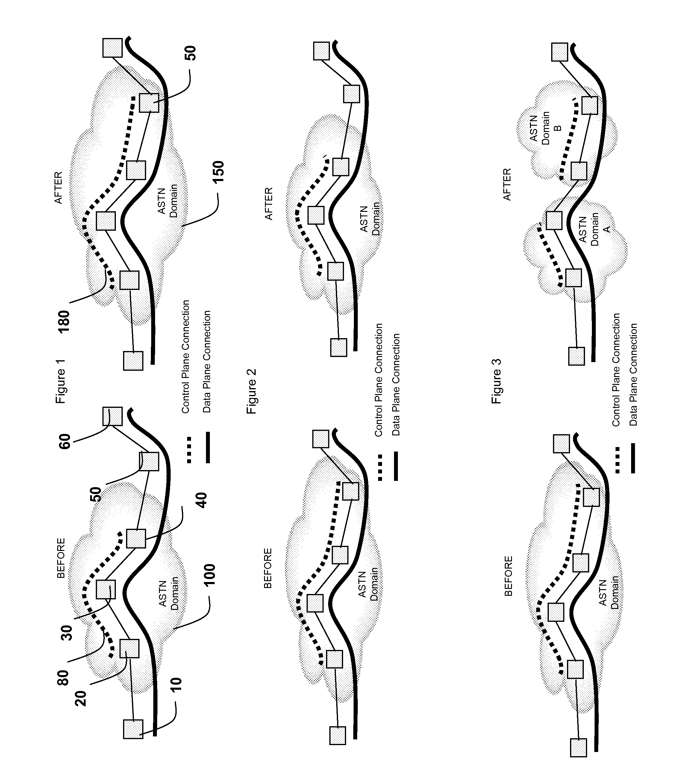
[0009] ii) then terminating the existing network control resources such that said data plane resources are fully transferred to the new set of control plane resources without disrupting said network connection.
[0013] In a further aspect, the present invention provides a method for changing the extent of data plane resources controlled by a control plane for a network connection which spans a contiguous set of nodes, said network connection controlled by existing network control resources, said method comprising the steps of: i) Creating a new set of control plane resources for said network connection such that said data plane resources are shared with said existing network control resources; and ii) then terminating the existing network control resources such that said data plane resources are fully transferred to the new set of control plane resources without disrupting said network connection. Such a method has particular benefits when at least some of said existing network control resources comprise existing control plane resources, or when the number of nodes controlled by said new set of control plane resources differs from the number of nodes controlled by said existing control plane resources. According to one embodiment, such a method includes creating connection control states for the new set of control plane resources on every node; and mapping the existing data plane resources to each new connection control state.

Problems solved by technology

However, these adjustments do affect the control plane and / or network management systems.

Method used


Image

  • Method and apparatus for non-disruptive call modification
  • Method and apparatus for non-disruptive call modification
  • Method and apparatus for non-disruptive call modification

Examples


Embodiment Construction

[0032] Exemplary embodiments of the invention will be described with reference to the example of an ASON control plane, as described in the Recommendation G.8080 / Y.1304, Architecture for the Automatically Switched Optical Network (ASON), which is a published ITU-T Document, which is hereby incorporated by reference in its entirety. However, it should be noted that the invention is also applicable to control planes for other protocols and networks, including ATM, Telephony, Frame Relay, ISDN, MPLS, GMPLS and X.25. Note that ASON and ASTN are used interchangeably in this specification. The term “connection” as used includes the definition found in ITU-T Recommendation G.805 (2000), “Generic functional architecture of transport networks” and also used in ITU-T Recommendation G.8110 / Y.1370 (2005), “MPLS layer network architecture”, both of which are hereby incorporated by reference.

[0033] Furthermore, we discuss embodiments of the invention with reference to modifying the span of contr...


PUM


Abstract

A method and system for changing the extent of data plane resources controlled by a control plane for a network connection which spans a contiguous set of nodes controlled by existing network control resources is disclosed. This is done in a non-disruptive manner. This typically involves two steps: i) Creating a new set of control plane resources for said network connection such that said data plane resources are shared with said existing network control resources; and ii) then terminating the existing network control resources such that said data plane resources are fully transferred to the new set of control plane resources without disrupting said network connection. The existing network control resources can be either a control plane resource or a non control plane resource. An example of a non control plane resource is network management software (e.g., an OSS (Operation Support System)), which forms part of the Management Plane. It should be noted that this does not need to be done for a complete end-to-end connection, but rather can be executed for the portion of the end-to-end connection which is to be controlled by the control plane.

Description

CROSS REFERENCE TO RELATED APPLICATIONS [0001] This application claims the benefit of priority of U.S. Provisional Patent Application No. 60 / 675,870 filed Apr. 29, 2005, which is incorporated herein by reference.FIELD OF THE INVENTION [0002] The present invention relates generally to telecommunication networks. More particularly, the present invention relates to such networks which utilize a control plane to control calls. BACKGROUND OF THE INVENTION [0003] Today's telecommunication networks are increasingly characterized by the separation of the control and data planes. That is, data plane connections used to transport traffic and their associated control plane connections used to manage the data plane connections are somewhat independent. [0004] All network operators over time increase or decrease the sizes of their networks, or alter the configuration their networks. There are many business reasons for this, including mergers, divestitures or re-organizations of carriers and ente...

Claims


Application Information

Patent Timeline
IPC IPC(8): H04L12/28H04L69/14
CPCH04L29/06027H04L47/10H04M3/2263H04L67/14H04Q3/0062H04L65/1083H04L65/80H04M7/06H04L65/1101
Inventor SKALECKI, DAREKSHEW, STEPHENCOUPAL, JEAN-PIERRE
Owner CIENA
Learn More