
Refrigeration/air-conditioning apparatus powered by an engine exhaust gas driven turbine

a technology of exhaust gas and refrigeration equipment, which is applied in the direction of light and heating equipment, transportation and packaging, and the operation mode of machines, etc., can solve the problem that the power requirements for adequate cooling cannot be m

Inactive Publication Date: 2006-11-02
EI DU PONT DE NEMOURS & CO
View PDF6 Cites 92 Cited by
  • Summary
  • Abstract
  • Description
  • Claims
  • Application Information

AI Technical Summary

Benefits of technology

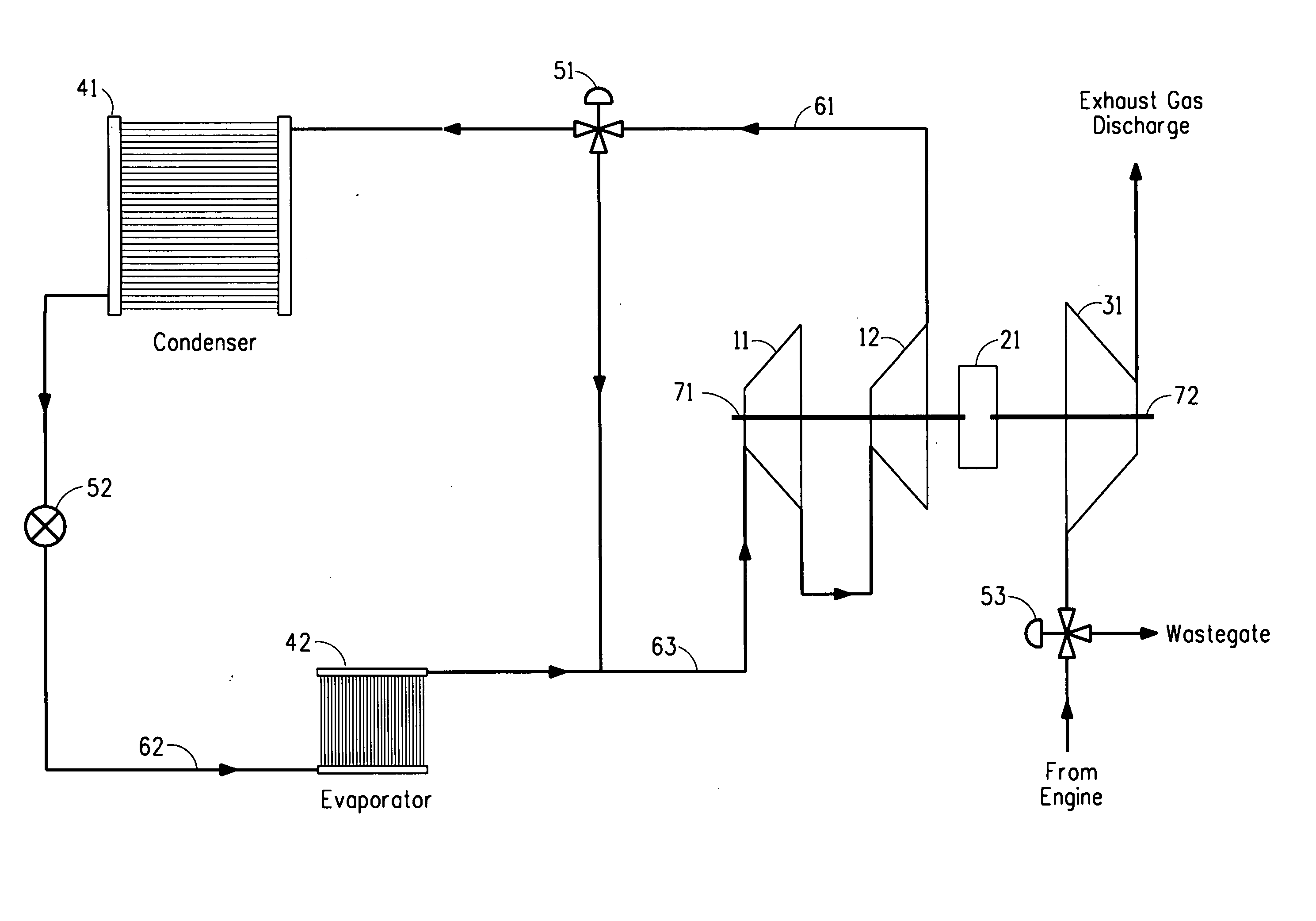
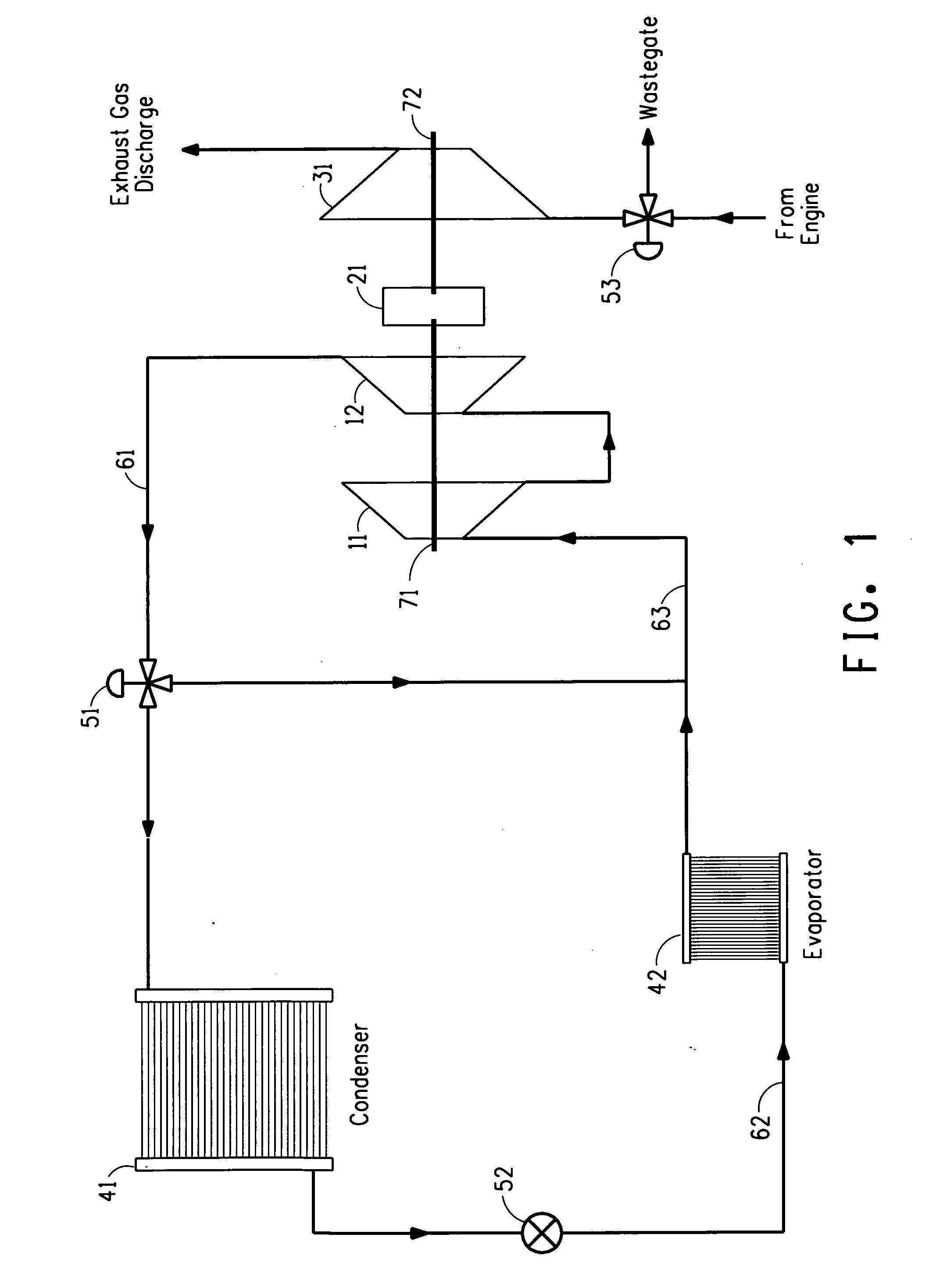
The present invention provides methods for controlling various aspects of a refrigeration or air-conditioning apparatus that uses a vapor compression refrigeration system powered by an engine exhaust gas driving turbine. These include adjusting the amount of exhaust gas entering the turbine to control compressor speed, which can affect both cooling capacity and efficiency. Additionally, changing the engine idling speed while operating the air conditioner can further improve performance. Overall, these techniques allow for better management of energy usage and improved operational efficiencies within such systems.

Problems solved by technology

The technical problem addressed in this patent text is the need for a new system to cool the air in the passenger compartment of an automobile that is not dependent on the use of ambient air and can meet the power requirements for mini-centrifugal compressors, so that low GWP refrigerants can be used. The current system uses a belt and pulley system that has inefficiencies and is difficult to speed up, making it difficult to use low GWP refrigerants.

Method used


Image

  • Refrigeration/air-conditioning apparatus powered by an engine exhaust gas driven turbine
  • Refrigeration/air-conditioning apparatus powered by an engine exhaust gas driven turbine

Examples


example

[0077] In this Example, a refrigeration apparatus using PEIK (perfluoroethylisopropylketone) as refrigerant to produce cooling capacity of approximately 1.5 tons at an impeller speed of 40,000 rpm is illustrated. The conditions assumed for this example are:

Evaporator temperature 40.0° F. (4.4° C.)Condenser temperature110.0° F. (43.3° C.)Liquid subcool temperature 10.0° F. (5.5° C.)Return gas temperature 75.0° F. (23.8° C.)Compressor efficiency is 80%

[0078] These are typical conditions under which a mini centrifugal compressor performs. Table 1 below shows the enthalpy of the refrigerant gas as it leaves the evaporator, (H Evaporator Out), the enthalpy of the refrigerant gas as in enters condenser (H Condenser In), the change in enthalpy between the evaporator and compressor, (Delta Hi), and the change in enthalpy between the evaporator and compressor multiplied by 0.8). The table below also shows theoretical tip speed and impeller diameter for a refrigeration apparatus.

TABLE 1HH...


PUM


Abstract

The present invention relates to a refrigeration or air-conditioning apparatus which utilizes a vapor compression refrigeration system having a refrigerant circulating therethrough that comprises a compressor powered by an engine exhaust gas driven turbine. A mini centrifugal compressor may advantageously be used with such an apparatus, thus allowing the use of low GWP refrigerants. The present invention further relates to methods for powering a compressor, such as a mini-centrifugal compressor, in a refrigeration or air-conditioning apparatus, and methods for controlling compressor surge, impeller speed and cooling capacity.

Description


Claims


Application Information

Patent Timeline
Owner EI DU PONT DE NEMOURS & CO
Learn More