
Screw-device for anastomosis

a technology of anastomosis and screw device, which is applied in the direction of surgical staples, catheters, mechanical equipment, etc., can solve the problems of short warm ischemia before cell death, high complexity of operation, and delicate instruments

Inactive Publication Date: 2006-10-26
UMC UTRECHT HLDG BV
View PDF3 Cites 17 Cited by
  • Summary
  • Abstract
  • Description
  • Claims
  • Application Information

AI Technical Summary

Benefits of technology

The present invention is a device called the SCREW-DEVICE that allows for easy and quick vascular anastomosis without the need for a suture. The device can be easily applied to the vessel wall and results in a smooth joint without any creases in the vessel wall. It can be used in various surgical procedures involving vascular problems and can be combined with existing laser technologies for non-occlusive opening of the receptor vessel.

Problems solved by technology

When there is a discrepancy between demand of oxygen or nutrients to the cell and the delivery capacity of the bloodstream to the cell, there is cell damage or even cell death. in some vital organs this warm ischemia before cell death is very short.
These highly complex operations require a competent surgical team, delicate instruments, advanced microsurgical equipment, magnifying loops, or—for neurosurgeons—an operating microscope.
This technique of suturing is time consuming and it demands extremely advanced microsurgical skills.
Moreover, it never results in a completely smooth joint, the stitches producing microscopic creases in the vessel wall.
Most of these devices are complex and time-consuming to apply (for example, in brain-surgery, a microvascular anastomosis takes on average, twenty to thirty minutes).
During this time, there is a high risk of bleeding and infection in all forms of microvascular surgery mentioned above.

Method used


Image

  • Screw-device for anastomosis
  • Screw-device for anastomosis
  • Screw-device for anastomosis

Examples


Embodiment Construction

[0016] Form: There are five main forms.

[0017] 1. Single-Ended Screw-Device.

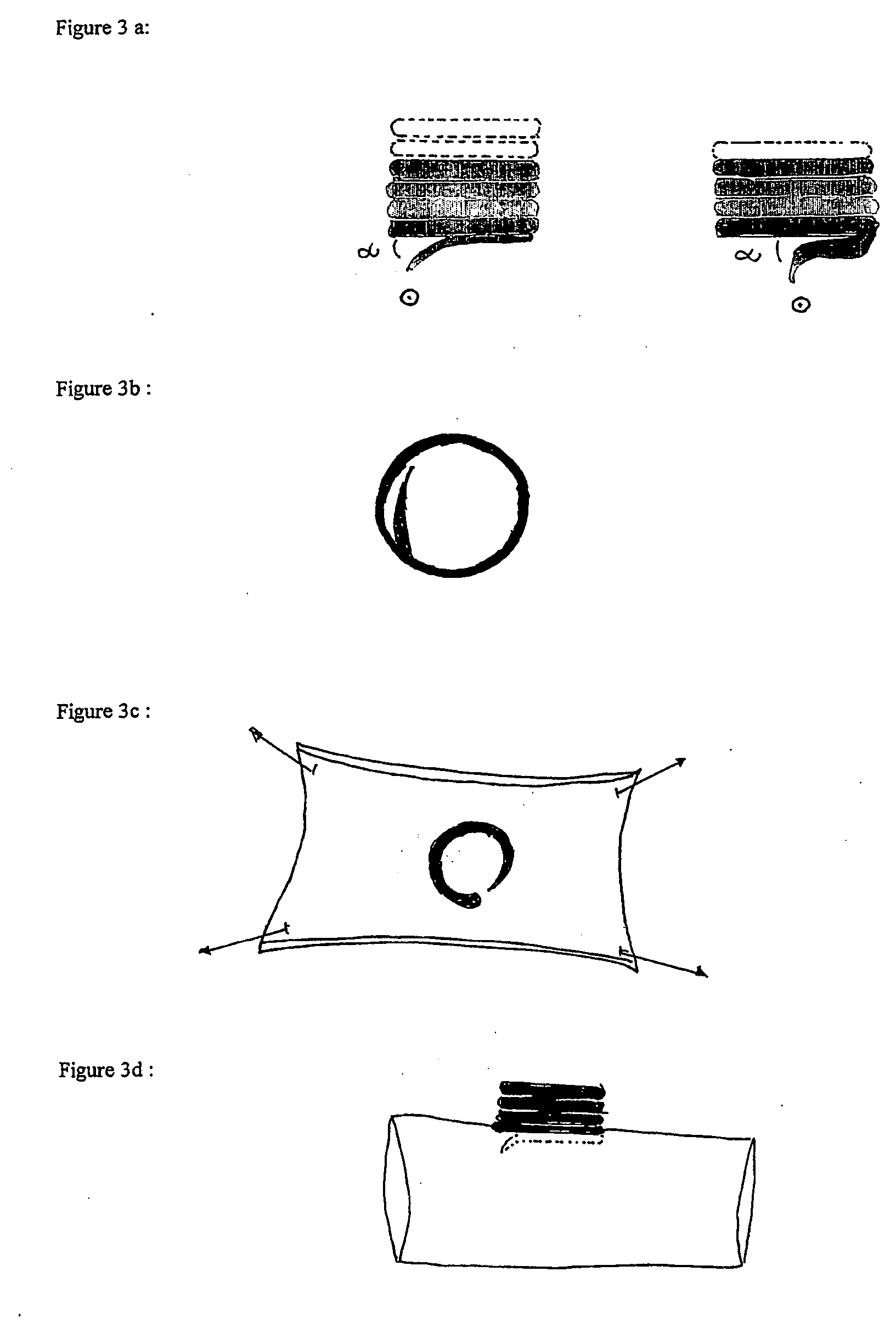
[0018] This device is a spring with four to six windings guaranteeing elasticity. The first three windings are closely adjacent, i.e., there is just the smallest space between them (the space enabling the SCREW-DEVICE to dig itself into the vessel wall). On the one end of the SINGLE-ENDED SCREW-DEVICE there is an extremely sharp end, meant to perforate the vessel wall. The other end is blunt.

[0019] The sharp end is round, i.e., non-cutting but capable of perforating the vessel wall. The sharp, round point is bent inwardly and downwardly in an angle of 10 to 20 degrees (a) (see FIG. 3a, 3b, 3c, 3d). Alternatively, this sharp, round, non-cutting point may bend downwardly in an angle of 90 degrees (a). In this case, the end resembles a corkscrew, but the end is not situated in the middle of the final winding but rather on the periphery.

[0020] 2. Double-Ended Screw-Device / Ring-Form.

[0021] This device is a sp...


PUM


Abstract

The present invention, the screw-device, is a mechanical device for anastomosing hollow tube-like structures in the human body, such as blood vessels, bowels and ureters. It is thus not restricted to (micro-)vessels. It can be used in every surgical operation dealing with anastomosis and bypass operations. It allows anastomosing end to side or side to side. The screw-device is very easy to apply onto the vessel wall. Screwing is a fast technique saving operating time and requiring only basic microsurgical skills. The manufacturing is easy. Another advantage is that the screw-device can be mounted onto the receptor vessel without first opening and / or occluding this vessel. Later on, the receptor vessel wall can be opened with laser or scalpel. It should be understood that the foregoing is illustrative and not limiting, and that modifications may be made by those skilled in the art, without departing from the scope of the invention.

Description

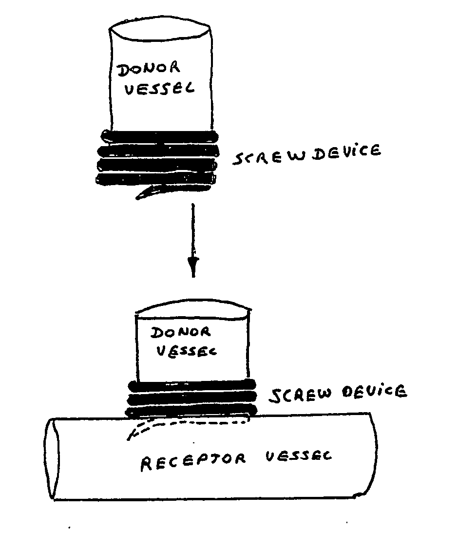
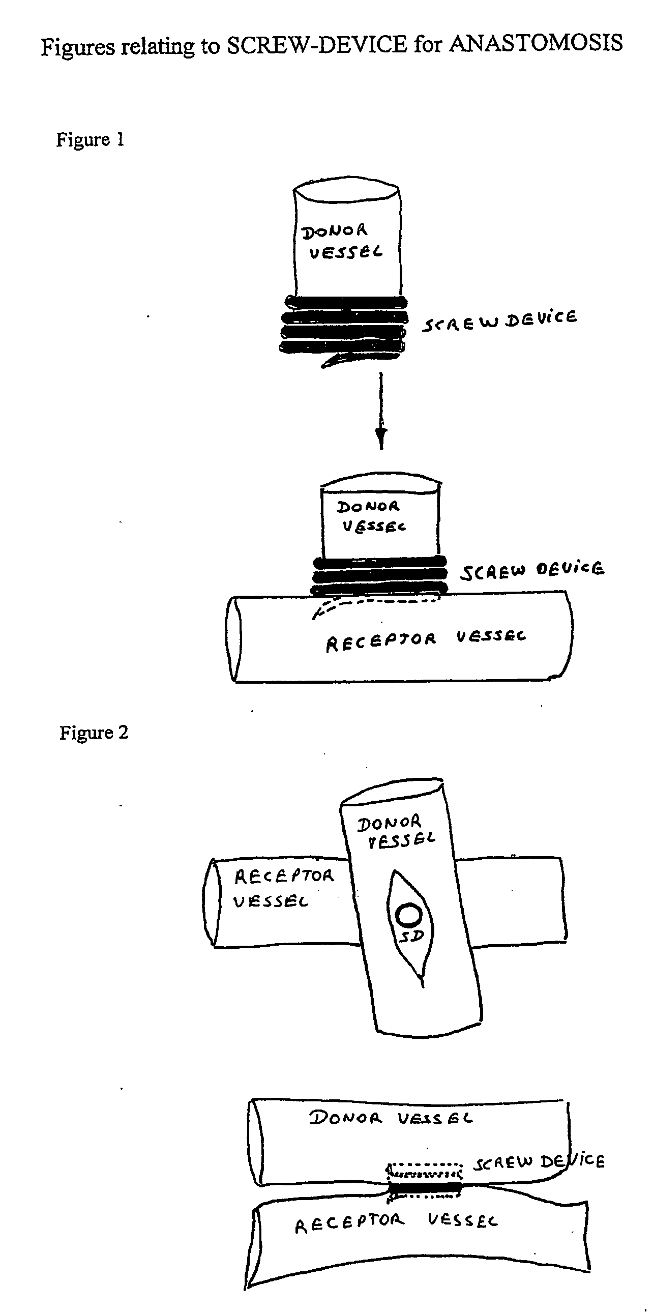
[0001] This application is a continuation of PCT application no. PCT / BE2003 / 000126, designating the United States and filed Jul. 22, 2003; which claims the benefit of the filing date of PCT application no. PCT / BE03 / 00074, filed Apr. 28, 2003, both of which are hereby incorporated herein by reference.DESCRIPTION [0002] 1. Technical Field [0003] The present invention relates to an anastomosis device, more particularly, the SCREW-DEVICE is capable of anastomosing the end of a blood vessel to the side of another blood vessel (end to side—see FIG. 1) or the side of a blood vessel to the side of another blood vessel (side to side—see FIG. 2). BACKGROUND ART [0004] Vital Cells (in brain, heart, muscles, organs) demand nutrition, oxygen, energy (glucose) at a constant supply. These components are found in the blood which runs in a healthy vascular system. As a pump system, the heart ensures the circulation of the blood(nutrients) through the body. When there is a discrepancy between demand ...

Claims


Application Information

Patent Timeline
Patent Type & Authority Applications(United States)
IPC IPC(8): A61B17/08A61B17/00A61B17/064A61B17/11A61B17/34A61M25/02
CPCA61B17/0057A61M2025/0286A61B17/11A61B17/1114A61B17/3415A61B17/3423A61B2017/00004A61B2017/00867A61B2017/0648A61B2017/0649A61B2017/1107A61B2017/1135A61B2017/1139A61B2017/3488A61M25/02A61M25/04A61M39/0208A61M39/04A61M39/06A61B17/064
Inventor TULLEKEN, CORNELIS ANTONIUS FRANCISCUSMANSVELT BECK, HENDRICUS JACOBUSBREMMER, JOCHEM-PAULDE WINTER, ERWIN
Owner UMC UTRECHT HLDG BV
Learn More