
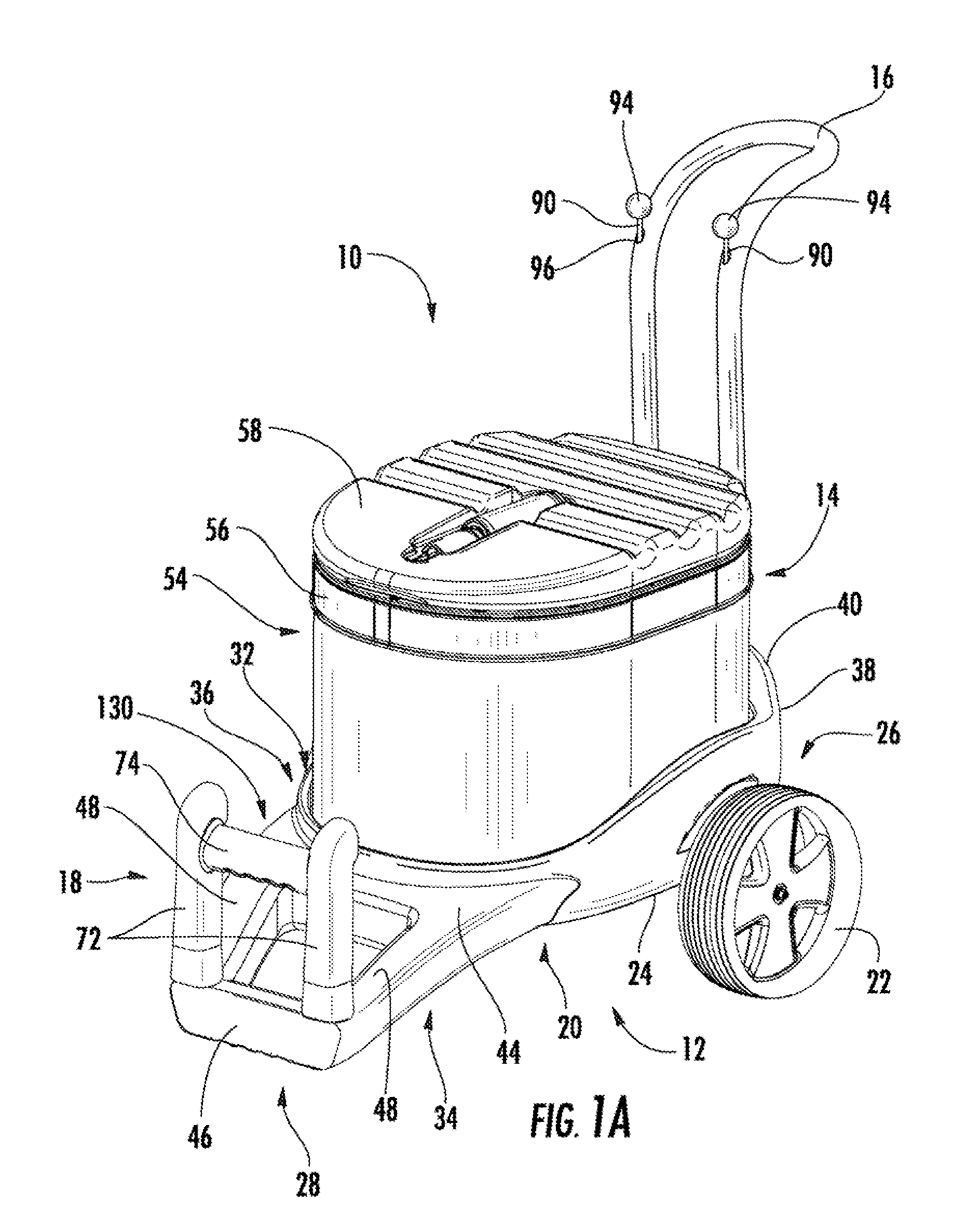
Travel cooler with cargo receiving area

Inactive Publication Date: 2006-10-26
M & C INNOVATIONS
View PDF67 Cites 31 Cited by
  • Summary
  • Abstract
  • Description
  • Claims
  • Application Information

AI Technical Summary

Benefits of technology

[0023] A travel cooler in accordance with a second aspect of the invention includes a wheeled platform and an insulated container. The wheeled platform includes a base and a plurality of wheels mounted to the base for rolling movement of the platform. The insulated container includes an inflatable wall and a valve for inflating of the wall. The insulated container is disposed on the base in fixed disposition relative to the base for safe transportation of the insulated container on the wheeled platform.
[0024] In a variation of this aspect, the travel cooler comprises a wheeled platform and an insulated container. The wheeled platform includes a base, a handle attached to the base, and a plurality of wheels mounted to the base for rolling movement of the platform by the handle. The insulated container includes inflatable sidewalls and at least one valve for inflating of the sidewalls. The insulated container is disposed on the base in fixed disposition relative to the base for safe transportation of the insulated container on the wheeled platform.
[0038] In a variation of this aspect, the travel cooler comprises a base, a plurality of wheels mounted to the base for rolling movement of the base, an insulated container supported by the base and defining an interior, insulated space for receiving and preserving perishable food items, and a retaining member mounted to the base and configured to move between a protracted position relative to the insulated container, wherein the retaining member and the insulated container define a cargo receiving area there between for receiving items for transport, and a retracted position relative to the insulated container, wherein the retaining member is disposed proximate the insulated container such that the cargo receiving area is substantially eliminated.

Problems solved by technology

It is often the situation that transporting the desired items to the beach is inconvenient and cumbersome.
Indeed, it often requires many trips back and forth from a car or hotel room to a particular spot on the beach.
Such known devices do not generally include a mobile device that is capable of transporting both non-perishable items as well as perishable items, and such known devices generally do not include a sufficient capacity to transport all, or even most, of the items that a family or group will need for a day-long outing at the beach in a single trip.
An additional drawback to known devices is that such devices generally require a large amount of storage space when not used.
Further, these mobile devices take up relatively large amounts of space whenever they are transported for use.
This is particularly disadvantageous when the mobile devices are packed into the family car when going on the family vacation at the beach.
Because they are so large and bulky, they tend to consume a large portion of the available space in the car, thereby limiting the other items that can be taken on the vacation.
In addition to being disadvantageous for consumers, such devices also are less desirable to retailers, who have limited shelf space on which to display goods for sale.
Specifically, these devices do not provide sufficient capacity for transporting the number of items to be used for a family or group during a day at the beach.
Furthermore, these devices do not have a storage configuration that is smaller in volume than their use configuration.
However, such known devices do not include design features that aid in mobility of the devices, let alone design features that aid in the transport of non perishable items such as towels, chairs, umbrellas, games, lotions and sun screen products.

Method used


Image

  • Travel cooler with cargo receiving area
  • Travel cooler with cargo receiving area
  • Travel cooler with cargo receiving area

Examples


second embodiment

[0140] the present invention is shown in FIGS. 10A-10B. In this embodiment, the travel cooler 1100 is configurable into a transport configuration as shown in FIG. 10A, and a storage configuration as shown in FIG. 10B. The cooler 1100 includes a platform 1102 having forward wheels 1104 and rearward wheels 1106. The insulated container 1108 also is inflatable in this embodiment. The container 1108 is shown as fully inflated in FIG. 10A, wherein the transport configuration of the cooler 1100 is obtained. In FIG. 10A, an insulated interior space is defined within the container 1108 for receiving, for example, food supplies, beverages, and ice. The container preferably includes at least a double-wall construction with an enclosed space defined between substantially air-impermeable walls for receiving air in inflating the container. Air trapped within the double-wall construction provides thermal insulation to help maintain a low temperature within the compartment of the container despite...


PUM


Abstract

A travel cooler includes a base, a plurality of wheels mounted to the base for rolling movement of the base and an insulated container having sidewalls supported by the base and defining an interior, insulated space for receiving and preserving perishable food items. The base includes a portion that extends beyond at least one of the sidewalls to define a cargo receiving area for receiving items for transport. Additionally, or alternatively, an arm member is mounted to the base and configured to move between a retracted position to define a cargo receiving area and a protracted position substantially eliminating the cargo receiving area. Alternatively, a travel cooler includes a bracket removably mounted to an insulated container. The bracket defines the cargo receiving area for receiving items for transport exterior to the insulated container.

Description

CROSS-REFERENCE TO RELATED APPLICATIONS [0001] For purposes of the United States, the present application is a nonprovisional of, and claims priority under 35 U.S.C. § 119(e) to, U.S. Provisional Patent Application No. 60 / 674,622, filed Apr. 25, 2005, the entire disclosure of which is hereby incorporated herein by reference.COPYRIGHT STATEMENT [0002] All of the material in this patent document is subject to copyright protection under the copyright laws of the United States and of other countries. The copyright owner has no objection to the facsimile reproduction by anyone of the patent document or the patent disclosure, as it appears in the Patent and Trademark Office patent file or records, or other governmental authority or agency, but otherwise reserves all copyright rights whatsoever. BACKGROUND OF THE INVENTION [0003] When spending a day at the beach, a family or group generally has many items that they wish to take with them to the beach. Such items may include towels, chairs,...

Claims


Application Information

Patent Timeline
IPC IPC(8): B62B3/02B62B1/00B62B3/00B62B7/02
CPCA45C5/14B62B3/003A45C11/20B62B1/006B62B1/04B62B3/022B62B3/10B62B3/16B62B5/06B62B5/061B62B5/067B62B2202/52B62B2204/06B62B2206/02B62B2206/04F25D3/06A45C7/004Y02A40/963
Inventor VANDERBERG, MATTHEW ALEXANDERKOVACEVICH, IAN D.BIZZELL, DANIEL LEEHOY, CHRIS
Owner M & C INNOVATIONS
Learn More