
Rack system for housing animals in cages having different widths

a rack system and cage technology, applied in the field of rack systems for housing animals, can solve the problems of single width of cages waste of valuable space, etc., and achieve the effects of saving time and space, facilitating placement, and maintaining proper air flow

Active Publication Date: 2006-10-26
LAB PROD LLC
View PDF12 Cites 28 Cited by
  • Summary
  • Abstract
  • Description
  • Claims
  • Application Information

AI Technical Summary

Benefits of technology

[0013] Embodiments of the present invention satisfy these and other needs. Generally, embodiments of the invention are directed to a rack system wherein the rack has shelves that can facilitate placement of, for example, one wide cage, or two narrow cages on each section of a shelf, preferably while still maintaining proper air flow into and out of the cages. By employing the invention, lab personnel may combine both wide and narrow cages within the same rack, thus saving time and space by not having to rely on two separate racks if the use of different sized cages is desired.

Problems solved by technology

However, due to the manner in which the cage is positioned within the rack, only a single width of cage may be accommodated by the rack.
This strategy, however, typically leads to a waste of valuable space.
Additionally, two different racks may be used, each rack accommodating a different size cage, but again, this strategy also tends to lead to the wasting of valuable space.
Furthermore, it is undesirable to use an existing single cage size rack to house double racks.
A typical double cage cannot be inserted in the place of two single cages because of the brackets in between the two sections.
A modified double cage must be produced, which can cause further disadvantages.
However, because most cages are made of plastic, cutting out a portion of the cage can weaken the cage.
The cage can break, or bend in at the cut out because of the weight of the cage and its contents, ultimately leading to the cage falling off the rack.
Therefore, the extra weight may cause the brackets or the thin shelf above, from which the brackets extend, to bow.
Because the double cage would be hanging on the brackets, the bow in the brackets or shelf may also result in the cage falling off the rack.

Method used


Image

  • Rack system for housing animals in cages having different widths
  • Rack system for housing animals in cages having different widths
  • Rack system for housing animals in cages having different widths

Examples


Embodiment Construction

[0037] Embodiments of the invention are directed to a rack system wherein the rack has shelves having sections that can facilitate placement of one relatively wide cage, or a plurality of, preferably two, relatively narrow cages, on each section of a shelf. Preferably, the rack system allows for a beneficial air flow into and out of the cages.

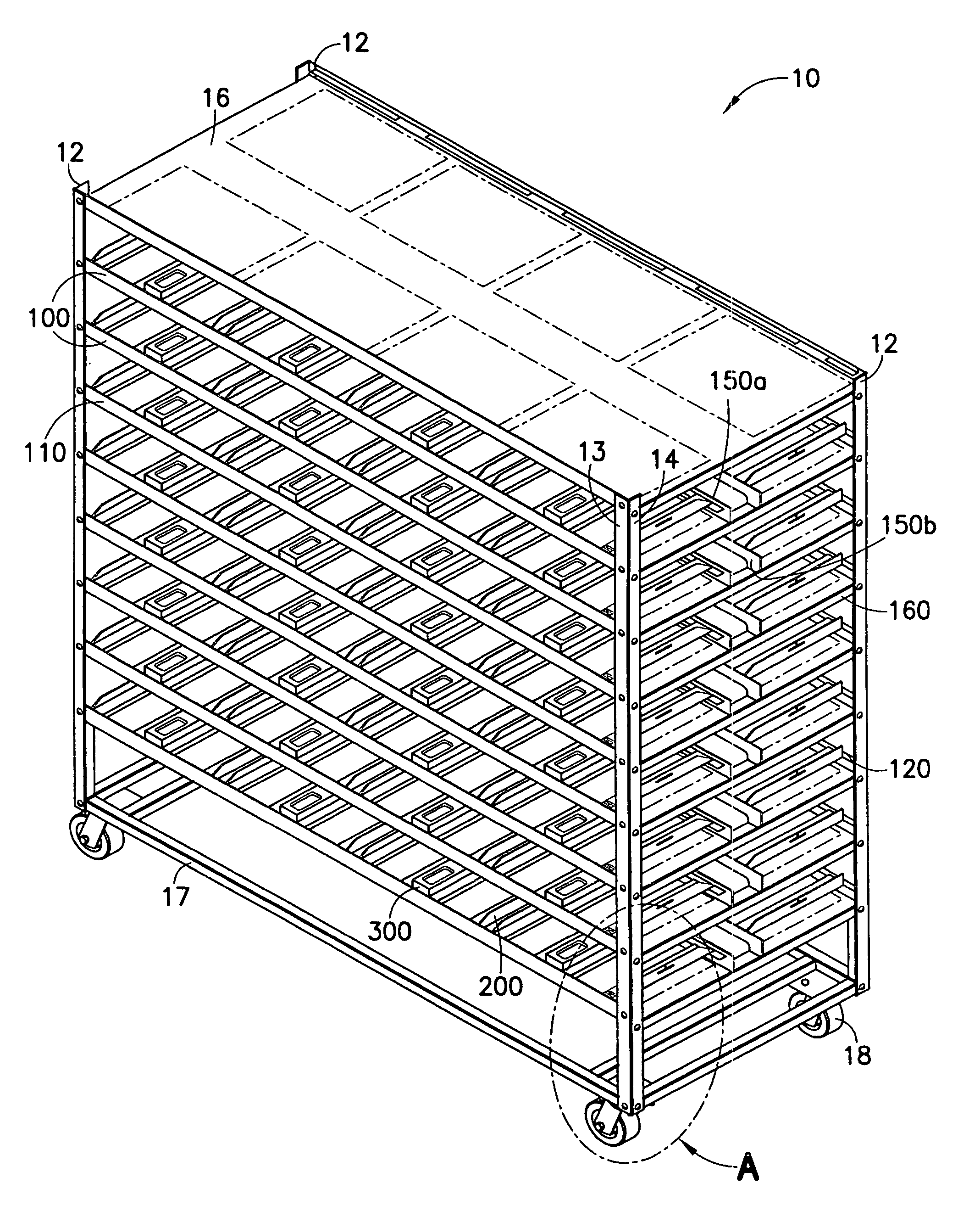
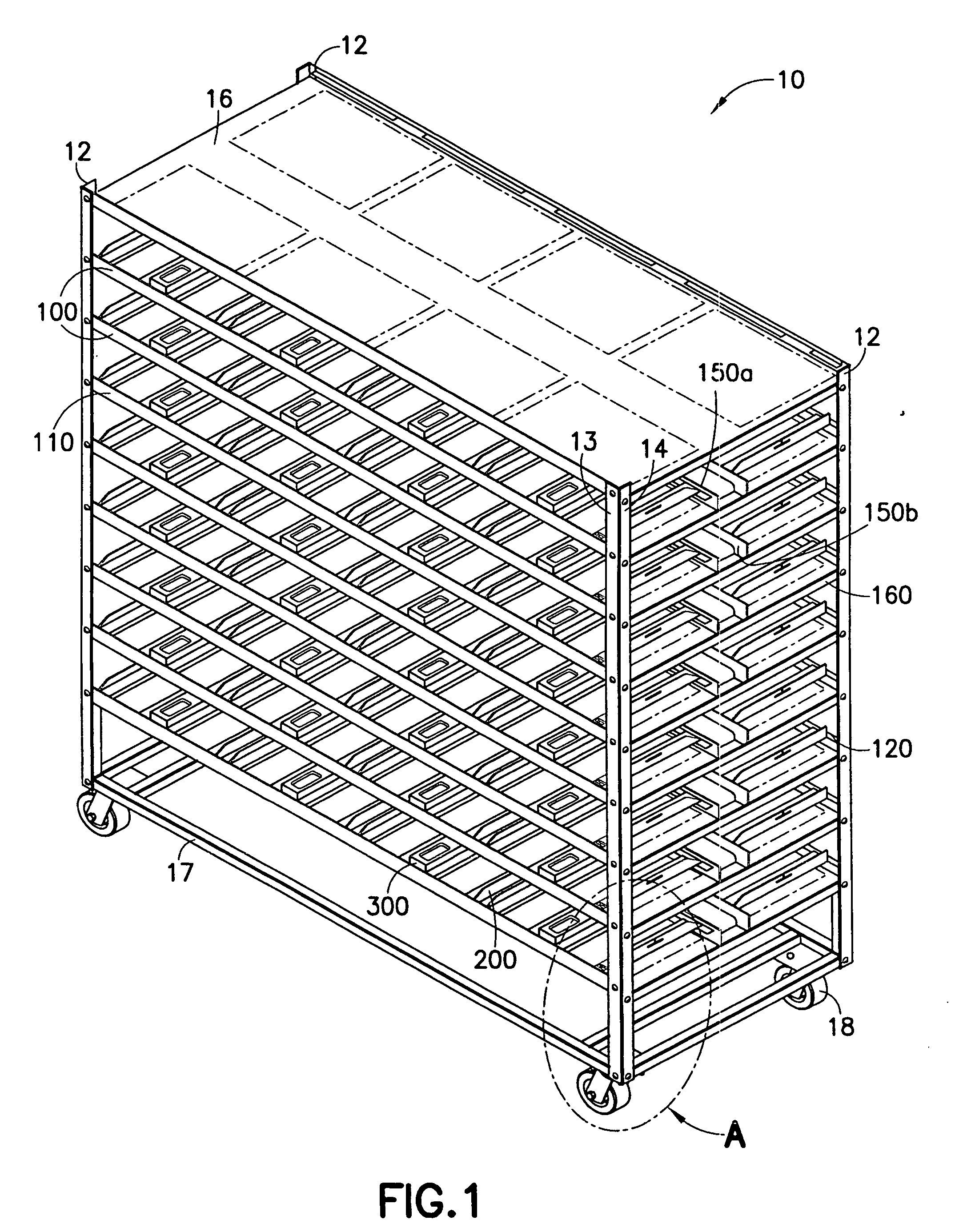
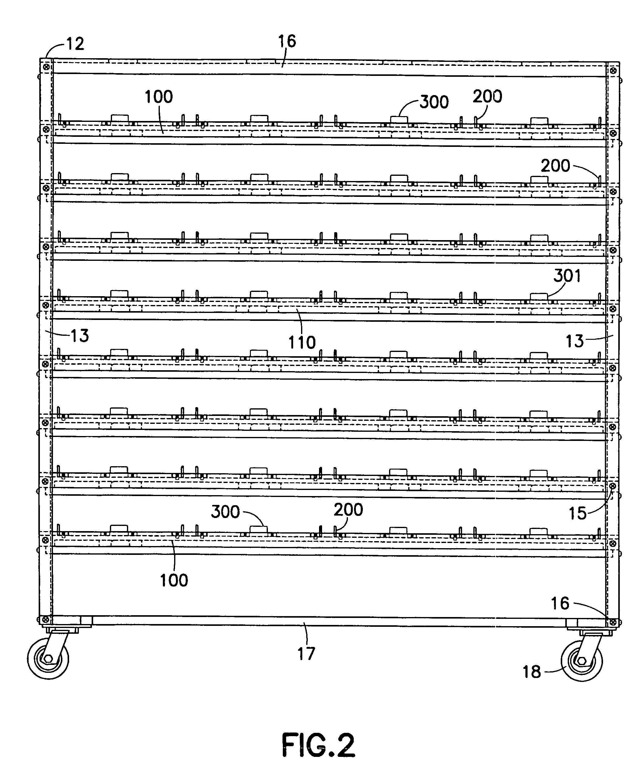
[0038] Reference is first made to FIGS. 1-4, wherein a rack system, generally indicated at 10, constructed in accordance with the invention is shown. Rack system 10 preferably includes an open rack having corner beams 12, a top 16, a bottom 17, and shelf assemblies 100. Shelf assemblies 100 preferably comprise a front panel 110, a rear panel 120, fixed runners 200, pivoting runners 300, support runners 150a,b, and shelf base 160. One known benefit of rack system 10 constructed in accordance with the invention is the fact that rack system 10 can house cages of varying sizes, namely single size cage 1 and double size cage 2 as shown in FIG. 15. ...


PUM


Abstract

Embodiments of a rack assembly for housing cages comprise at least one shelf, the shelf having a shelf section comprising a runner capable of being positioned in a least a first position and a second position. The shelf section is constructed and arranged to accommodate two cages having a first and second widths when the runner is positioned in the first position. The shelf section is constructed and arranged to accommodate a single cage having a third width when the runner is in a second position, the first and second widths being less than the third width.

Description

CROSS-REFERENCE TO RELATED APPLICATIONS [0001] This application claims the benefit of U.S. Provisional Application Ser. No. 60 / 619,249, filed on Oct. 15, 2004, entitled “RACK SYSTEM FOR HOUSING ANIMALS IN CAGES HAVING DIFFERENT WIDTHS”, which is hereby incorporated in its entirety by reference.BACKGROUND OF THE INVENTION [0002] 1. Field of the Invention [0003] The invention relates generally to a rack systems for housing animals. [0004] 2. Description of Related Art [0005] It is well known in the art to house laboratory animals, such as mice and rats, in cages. It is also well known in the art to house the cages on racks. These cages are typically suspended from the shelf above the cage via a rim or flange that extends outward from the top of the cage. The cages can be designed such that they are placed without a cage top into the rack, and ambient air is permitted to enter into the cage. Other cages can be ventilated, and, when placed in a rack, environmentally controlled (e.g., ai...

Claims


Application Information

Patent Timeline
IPC IPC(8): A01K1/03
CPCA01K1/031
Inventor GABRIEL, GEORGE S.CAMPBELL, NEIL E.MURRAY, DALEGERRINGER, RODNEYIRWIN, LYNNCRITES, BILL
Owner LAB PROD LLC
Learn More