
Capacitive touchpad with physical key function

a technology of capacitive touchpad and function, which is applied in the direction of contact mechanism, pulse technique, instruments, etc., can solve the problems of large consumption, and limited size of key-type input apparatus

Inactive Publication Date: 2006-10-19
ELAN MICROELECTRONICS CORPORATION
View PDF1 Cites 122 Cited by
  • Summary
  • Abstract
  • Description
  • Claims
  • Application Information

AI Technical Summary

Benefits of technology

[0007] The capacitive touchpad according to the present invention is like a physical key that changes the potential by pressing to trigger a key function. So the present invention has the advantages of a capacitive touchpad and a physical key.

Problems solved by technology

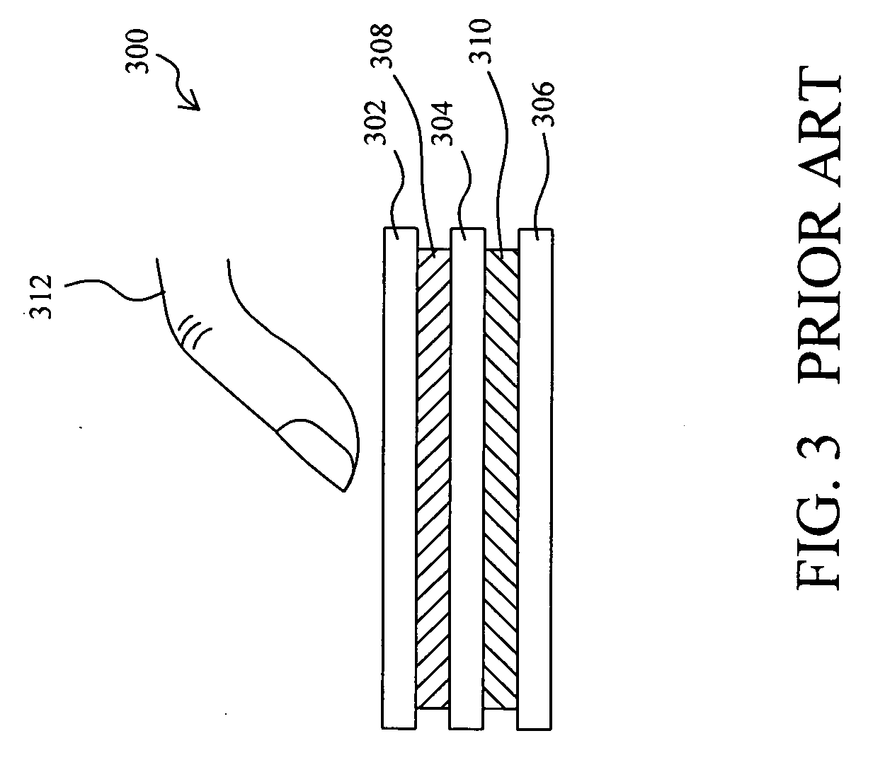
But the size of a key-type input apparatus is limited due to the key, and becomes the barrier to minimize an electronic device.
A capacitive touchpad also has to scan continuously to sense the position of the finger and thus consumes much.

Method used


Image

  • Capacitive touchpad with physical key function
  • Capacitive touchpad with physical key function
  • Capacitive touchpad with physical key function

Examples


Embodiment Construction

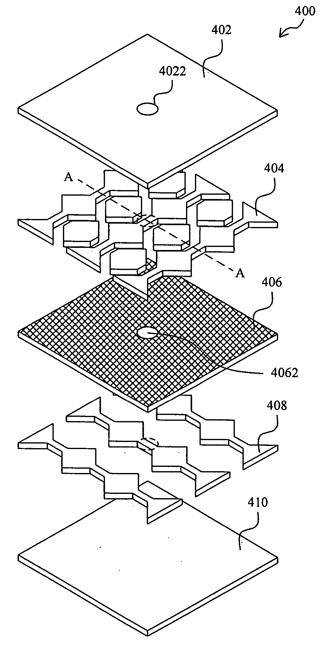
[0027]FIG. 4 is an exploded view of a capacitive touchpad 400 according to the present invention. FIG. 5A is a section view of the touchpad 400 along AA direction. In the capacitive touchpad 400, the conductive layers 404 and 408 used as Y-axis sensor and X-axis sensor are separated by the insulator layer 406 between the panel 402 and the substrate 410. As shown in FIG. 5B, in other embodiments, the insulator layer 406 may comprise a plurality of insulator balls 406′. The panel 302, conductive layers 404 and 408, and insulator layer 406 are all made of soft flexible material. The insulator layer 406 has a hole on the insulator layer 406. There is a key area 4022 on the panel 402 corresponding to the position of the hole 4062. When a user presses on the key area 4022, as shown in FIG. 6, the conductive layer 404 connects the conductive layer 408 through the hole 4022 of the insulator 406 and causes a change on the potential of conductive layer 404 or 408 and triggers a predetermined ...


PUM


Abstract

A capacitive touchpad with physical key function comprises a soft flexible first conductive layer; a second conductive layer; and a soft flexible insulator layer disposed between the first and the second conductive layers. The insulator layer has at least a through hole for the first conductive layer to connect to the second conductive layer while the touchpad is pressed and cause the voltages on the first or the second conductive layers to change and thus to trigger a predetermined key function.

Description

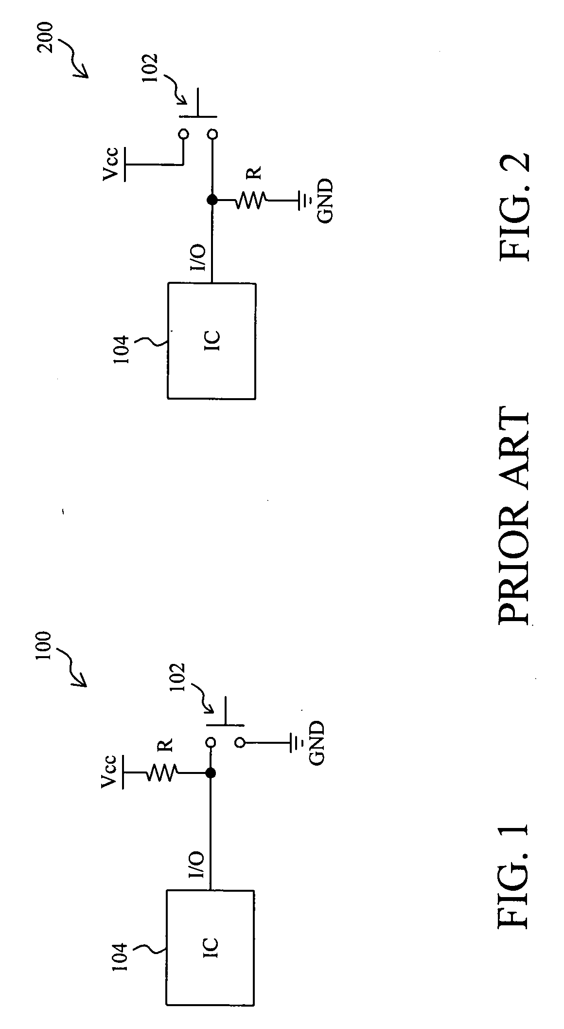
FIELD OF THE INVENTION [0001] The present invention is related generally to a capacitive touchpad, and more particularly, to a capacitive touchpad with physical key function. BACKGROUND OF THE INVENTION [0002] As shown in FIG. 1 and FIG. 2, a conventional key-type input apparatus 100 and 200 change the potential stage of I / O of an integrated circuit 104 by applying a force to press a key 102 to detect if the key 102 is pressed. When the key 102 is not pressed, the potential of the I / O of the input apparatus 100 is high; when the key 102 is pressed, the potential of the I / O is low. When the key 102 is not pressed, the potential of the I / O of the input apparatus 200 is low; when the key 102 is pressed, the potential of the I / O changes to high. Since the potential stage varies with the force to determine if the key is pressed, there's an advantage of precise operation and low power consumption. [0003] As technology develops, the volumes of electronic devices get smaller, especially por...

Claims


Application Information

Patent Timeline
IPC IPC(8): G09G5/00
CPCG06F3/044H01H13/807H01H2003/0293H01H2209/046H03K2217/960755H01H2225/002H01H2239/006H03K17/962H03K17/98H01H2211/006G06F3/0445G06F3/0446G06F3/0447
Inventor CHIEN, YUNG-LIEHLII, JIA-YIH
Owner ELAN MICROELECTRONICS CORPORATION
Learn More