
Method of adopting square voltage waveform for driving flat lamps

Inactive Publication Date: 2006-10-12
DELTA ELECTRONICS INC
View PDF12 Cites 0 Cited by
  • Summary
  • Abstract
  • Description
  • Claims
  • Application Information

AI Technical Summary

Benefits of technology

[0011] In view of the disadvantages of prior art, the primary object of the present invention is to provide a method of adopting square voltage waveform for driving a lamp, that is, a method of driving a flat lamp by a voltage of square waveform or a voltage of multi-step square waveform instead of conventional sinusoidal voltage, by which the over-pulse peak of the square waveform or multi-step square waveform is raised to a specific trigger voltage of the flat lamp for enabling the driving current of the flat lamp to be a pulse-type current capable of effectively overcoming the dielectric barrier thereof, whereas the pulse-type current is generated starting at the steep fronts of the square voltage, i.e. at the ascending / descending point of each over-pulse peak of the square wave, so that the luminous efficiency of the flat lamp can be enhanced while reducing the operating temperature of the same.

Problems solved by technology

LCDs are nonemissive light devices, which means they do not produce any form of light.
It is inevitable that a backlight module with diffuser will have to face the problems of increasing overall thickness and operating temperature.
Moreover, the brightness decay of each cold cathode lamp is speeding up after long-hour high-temperature operation while the speed of the decaying can be varied from one cold cathode lamp to another that is going to cause a high brightness LCD to suffer the phenomenon of uneven illumination.
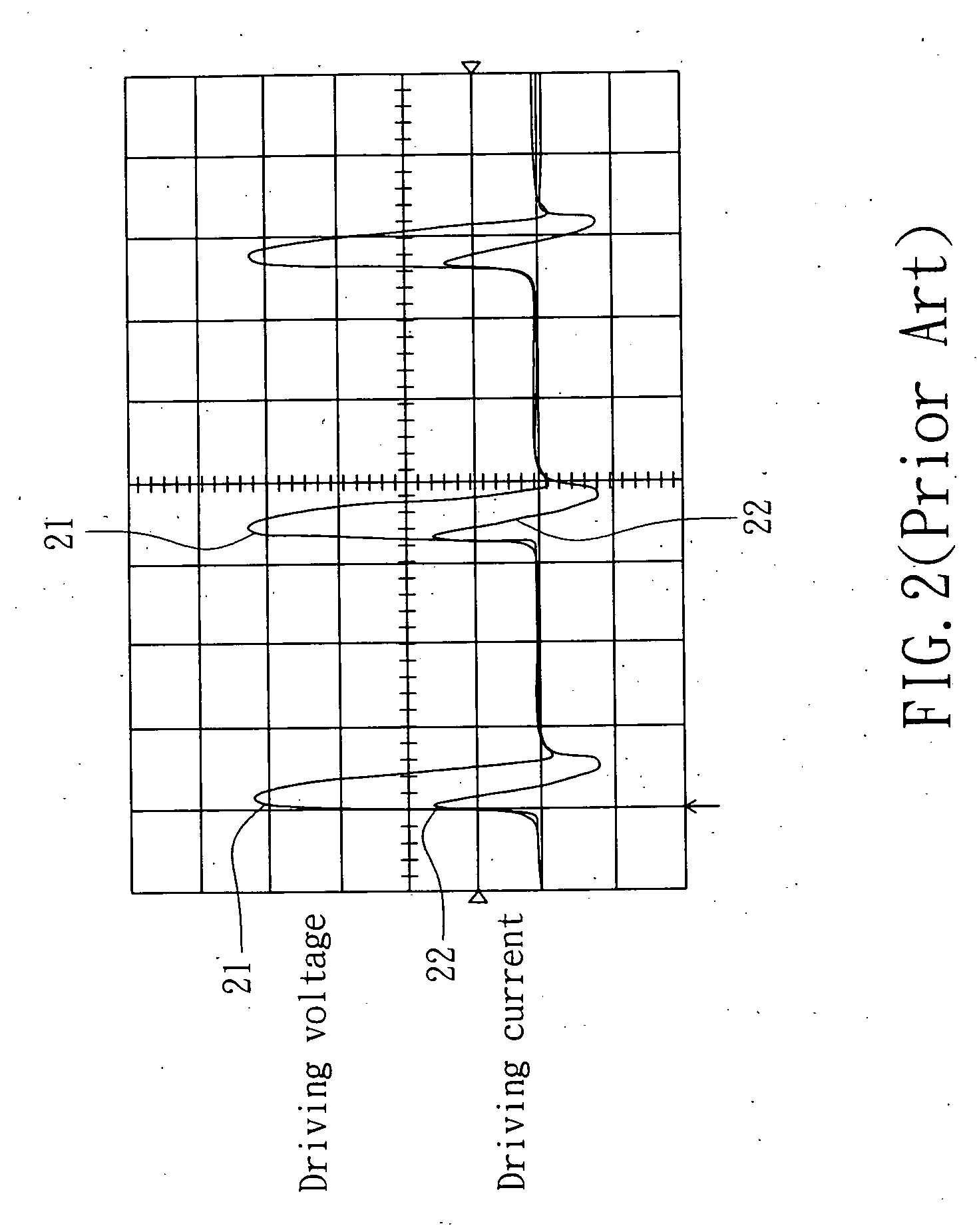
In FIG. 2, a single unipolar voltage pulse has been used to stress a flat lamp, however, this technique is not very efficient, as it does not result in large current transients through the device.
Because of that, not only the luminous efficiency of the flat lamp is reduced and the temperature of the flat lamp is increased, but also it will cause the electric arc generated in the flat lamp to be unstable.
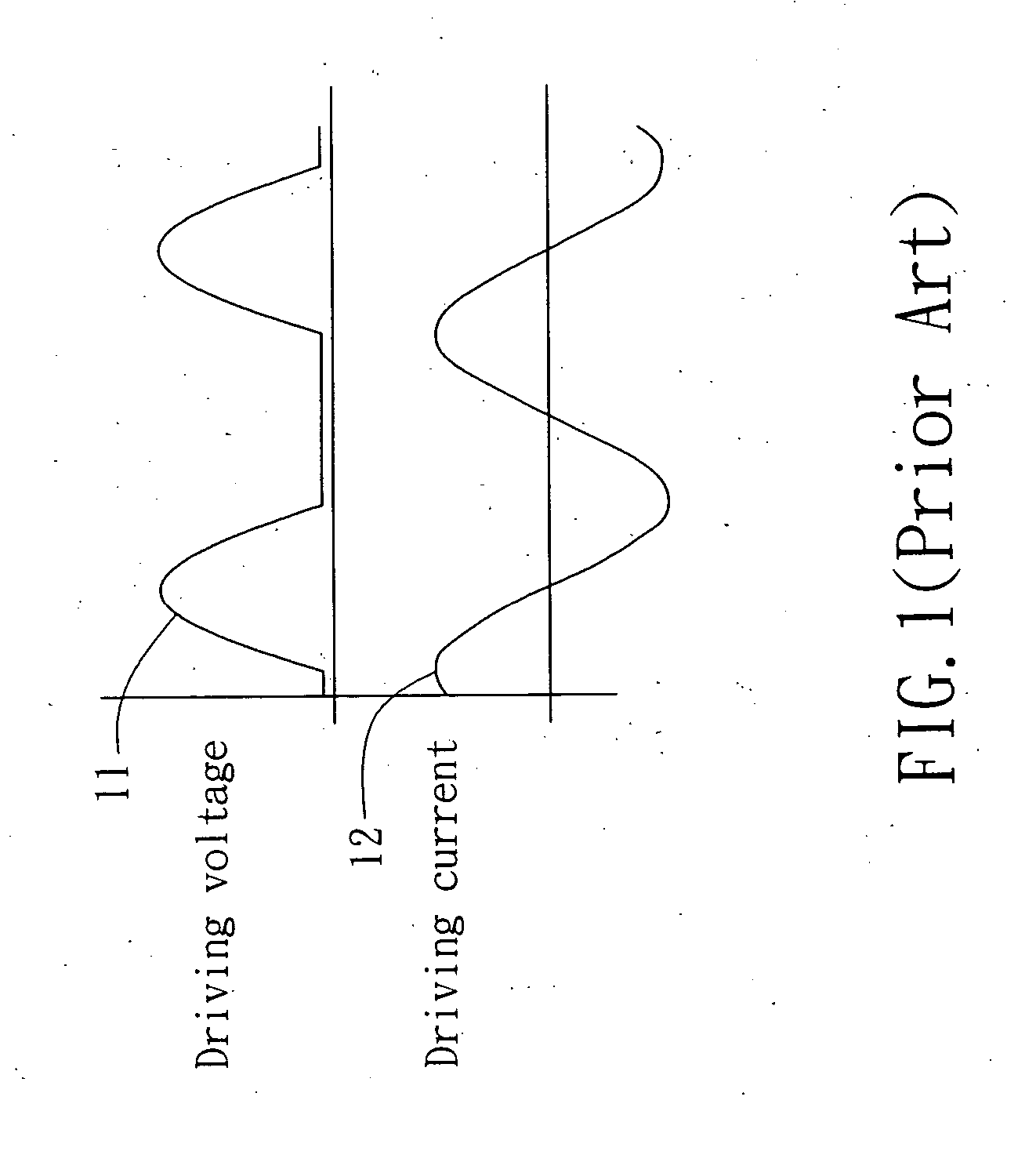
However, as the driving voltage is boosted, the corresponding electromagnetic interface (EMI) is also enhanced, such that as the backlight module using the foregoing flat lamp is operating, it is going to fail the relating official test of EMI / EMC, such as CE.
(2) The synthesized wave of trapezoid waveform formed at the high-voltage side of the transformer is going to cause the transformer to have addition circulating current, and thus there is also a power loss problem that must be overcome similarly by raising driving voltage.
However, the raised driving voltage will cause EMI problem.

Method used


Image

  • Method of adopting square voltage waveform for driving flat lamps
  • Method of adopting square voltage waveform for driving flat lamps
  • Method of adopting square voltage waveform for driving flat lamps

Examples


Embodiment Construction

[0025] For your esteemed members of reviewing committee to further understand and recognize the fulfilled functions and structural characteristics of the invention, several preferable embodiments cooperating with detailed description are presented as the follows.

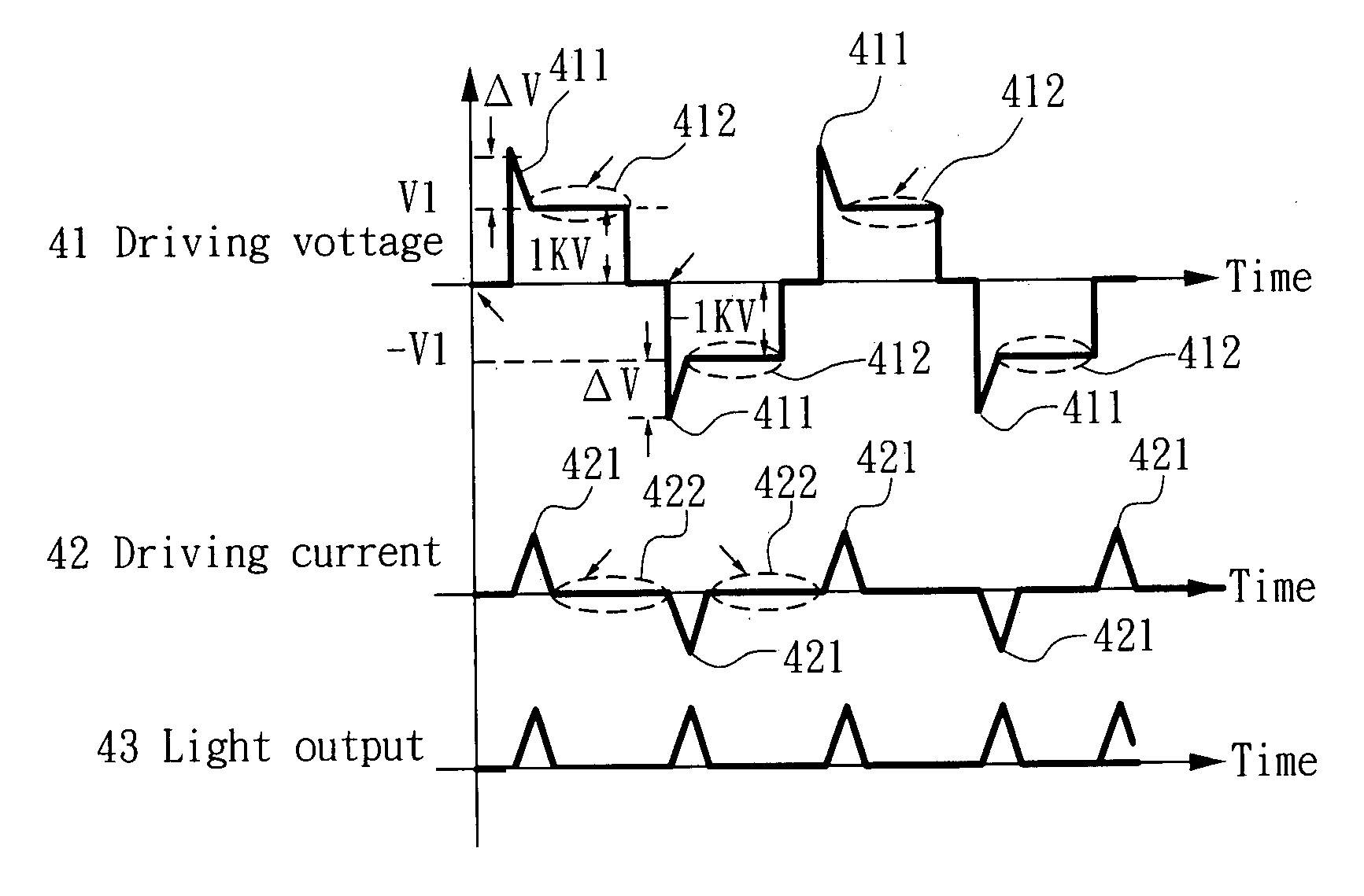
[0026] Please refer to FIG. 4, which shows the relation between light being emitted by a cold cathode flat lamp and its driving voltage / driving current according to the present invention. As seen in FIG. 4, each period of the driving voltage 41 is composed of a sub-period of trigger voltage 411 and a sub-period of maintain voltage 412, which correspond to a sub-period of discharging current 421 and a sub-period of no current 422 of a period of driving current 42 corresponding thereto. It is noted that each sub-period of discharging current 421 is related to a corresponding light-emitting period of the flat lamp 43. The present invention provides a method for driving a flat lamp, the flat lamp being the light source of any c...


PUM


Abstract

The present invention relates to a method adopting square voltage waveform for driving a flat lamp used as the light source of a flat panel display or a common light fixture, the method comprising steps of: using a power unit to convert direct current into voltage of square waveform; using a voltage booster to raise the crest of the square voltage waveform to a specific trigger voltage capable of turning on the flat lamp; and providing a pulse-type current while enabling the pulse-type current to be just larger enough to break the dielectric barrier of the flat lamp.

Description

FIELD OF THE INVENTION [0001] The present invention relates to a method of adopting square voltage waveform for driving a lamp, and more particularly, to a method of driving a flat lamp by a voltage of square waveform or a voltage of multi-step square waveform instead of conventional sinusoidal voltage, by which the over-pulse peak of the square waveform or multi-step square waveform is raised to a specific trigger voltage of the flat lamp for enabling the driving current of the flat lamp to be a pulse-type current capable of effectively overcoming the dielectric barrier thereof, whereas the pulse-type current is generated starting at the steep fronts of the square voltage, i.e. at the ascending / descending point of each over-pulse peak of the square wave, so that the luminous efficiency of the flat lamp can be enhanced while reducing the operating temperature of the same. BACKGROUND OF THE INVENTION [0002] LCDs are nonemissive light devices, which means they do not produce any form ...

Claims


Application Information

Patent Timeline
IPC IPC(8): H05B37/02
CPCY02B20/22H05B41/2806Y02B20/00
Inventor HUNG, JIN-CHYUANHUANG, QIUKAYING, JIANPINGCHOU, CHING-HOPAN, KUNG-TUNGFRAN, YUI-SHIN
Owner DELTA ELECTRONICS INC
Learn More