
Drum washing machine

Active Publication Date: 2006-10-12
SAMSUNG ELECTRONICS CO LTD
View PDF4 Cites 12 Cited by
  • Summary
  • Abstract
  • Description
  • Claims
  • Application Information

AI Technical Summary

Benefits of technology

[0015] Therefore, one aspect of the invention is to provide a drum washing machine having an improved frame structure, the rigidity of which is sufficiently maintained to achieve various external designs of the washing machine.
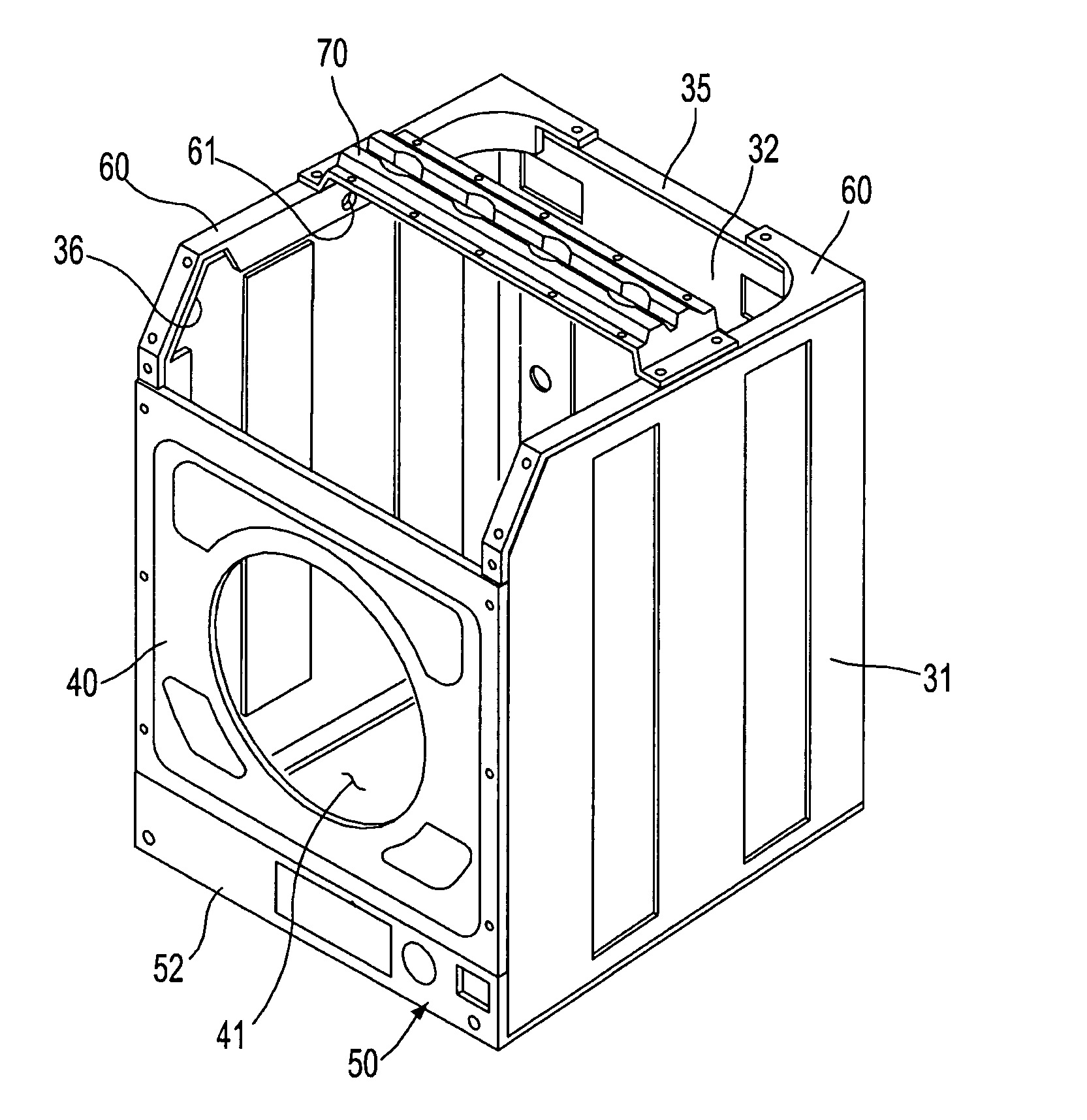
[0021] The front frame may be connected to the front surfaces of the side frames from portions thereof on the vertical portion to portions thereof adjacent to the top brackets so as to efficiently maintain the rigidity against force applied from the front of the side frames in the lateral direction, and may have an approximately regular tetragonal plate shape.

Problems solved by technology

Accordingly, when external force is applied to the frame structure or rotary force from the internal rotating component is applied to the frame structure, the frame structure cannot maintain sufficient rigidity against distortion.
Moreover, the frame structure of the conventional drum washing machine does not have frames installed on opened upper and lower portions of the main frame 1 for reinforcing the rigidity of the frame structure, thus having the low rigidity of upper and lower portions of the washing machine.
The sheathing members severely limit the design freedom of the drum washing machine so as to satisfy consumer's requirements.
In the conventional frame structure, the spring brackets 6 support only springs, and do not sufficiently reinforce the rigidity of the main frame 1, thus being incapable of sufficiently reinforcing the rigidity of upper corners of the main frame 1.
The above problem is severe, as drum washing machine products are large-sized and a rotating body in the drum washing machine products is rotated at a high speed.

Method used


Image

  • Drum washing machine
  • Drum washing machine
  • Drum washing machine

Examples


Embodiment Construction

[0033] Reference will now be made in detail to the embodiment of the present invention, an example of which is illustrated in the accompanying drawings, wherein like reference numerals refer to like elements throughout. The embodiment is described below to explain the present invention by referring to the annexed drawings.

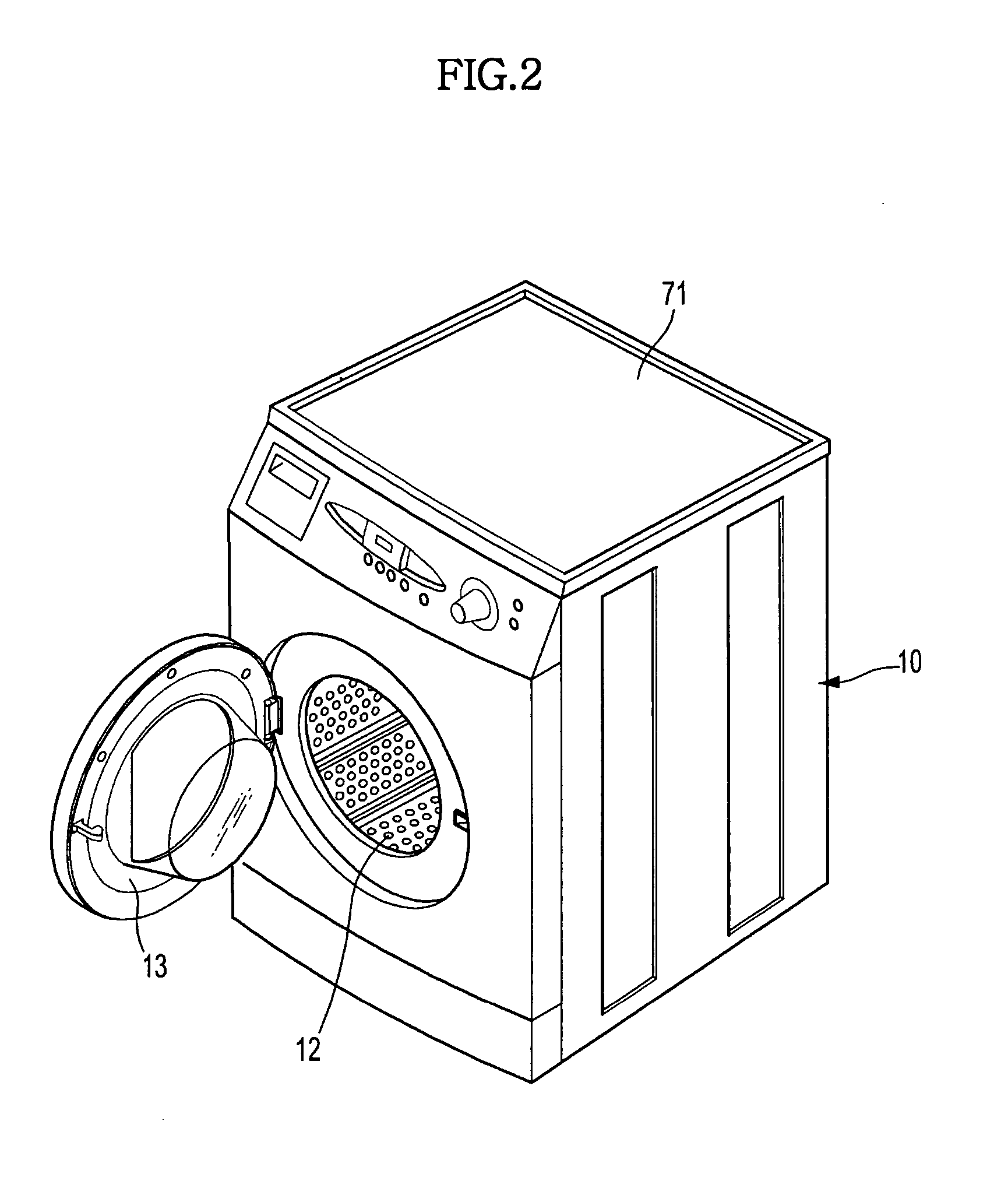
[0034]FIG. 2 is a perspective view of a drum washing machine of the present invention. FIG. 3 is a longitudinal sectional view of the drum washing machine of the present invention.

[0035] As shown in FIGS. 2 and 3, the drum washing machine of the present invention includes a housing 10 forming the external appearance of the drum washing machine, a tub 11 installed in the housing 10 for containing washing water, a drum 12 rotatably installed in the tub 11 for containing laundry to be washed, and a door 13 installed on the front surface of the housing 10 for opening and closing the opened front surface of the housing 10.

[0036] A water supply pipe 14 for supplying w...


PUM


Abstract

A drum washing machine having an improved frame structure, the rigidity of which is reinforced. The drum washing machine includes side frames forming side surfaces thereof, where inclined planes are formed between front and upper surfaces of the side frames so that additional frames for reinforcing the rigidity of upper parts of the side frames are respectively connected to the upper surfaces of the side frames and upper regions of the front surfaces of the side frames. The drum washing machine further includes top brackets respectively connected to the upper surfaces, the inclined planes, and the upper regions of the front surfaces of the side frames for reinforcing the rigidity of upper parts of the side frames. The drum washing machine further includes a front frame, and a bottom panel or a top panel, connected to the side frames for reinforcing the rigidity of front, lower and upper parts of the side frames. The drum washing machine efficiently supports load increased according to large-scale and high-speed trends of the washing machine, and provides a frame structure capable of withstanding all loads without using a sheathing member, thus having various designs without limit.

Description

CROSS REFERENCE TO RELATED APPLICATION [0001] This application claims the benefit of Korean Patent Application No. 10-2005-28559, filed April 6, 2005 in the Korean Intellectual Property Office, the disclosure of which is incorporated herein by reference. BACKGROUND OF THE INVENTION [0002] 1. Field of the Invention [0003] The present invention relates to a drum washing machine, and more particularly, to a frame structure of a drum washing machine having improved rigidity characteristics of the frame so that the design of the drum washing machine can be variously modified. [0004] 2. Description of the Related Art [0005] A drum washing machine washes laundry by rotating a drum-type washing tub using a motor so as to lift and drop the laundry and washing water and to generate friction between the laundry and the washing water. Generally, the drum washing machine includes a frame for forming the overall external appearance of the washing machine and supporting internal components, such a...

Claims


Application Information

Patent Timeline
IPC IPC(8): D06F37/00D06F35/00D06F23/00
CPCD06F39/12D06F37/22D06F37/26D06F39/14
Inventor LEE, CHIN WONKANG, MYUNG SUNPANG, JANG HYUK
Owner SAMSUNG ELECTRONICS CO LTD
Learn More