
Wear assembly

a technology of wear members and wear parts, applied in the field of wear components, can solve the problems of reducing the service life of wear components, so as to maximize the potential carrying weight of buckets, reduce the weight of wear components, and facilitate replacement.

Inactive Publication Date: 2006-10-12
ESCO CORP
View PDF14 Cites 17 Cited by
  • Summary
  • Abstract
  • Description
  • Claims
  • Application Information

AI Technical Summary

Benefits of technology

[0003] In this industry, it is advantageous for wear members to possess the conflicting goals of being reliably locked in place during operation yet being easily replaced when worn. The arduous environments and especially the ever present shock loads hinder the realization of these contradictory goals. It is also beneficial to keep the weight of the wear members to a minimum in order to maximize the potential carrying weight of the buckets. Further, it is generally desirable to limit costs, difficulties of use, and risks of failure.
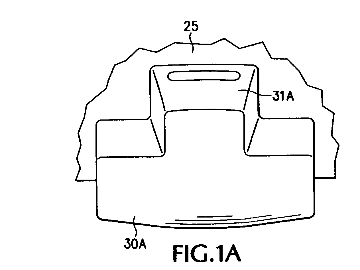
[0005] To improve on this assembly, a stabilizer is provided to restrain the lower leg of the wear member, which previously freely extended along the bottom of the bucket. In this way, the stress in the wear member can be reduced in a simple, cost-effective, and low-weight manner. While leg restraints have been used in past assemblies, they have been limited to use facilitating the interaction of the lock and the leg. See, for example, U.S. Pat. Nos. 5,553,409; 5,052,134; and 3,736,664.

Problems solved by technology

The arduous environments and especially the ever present shock loads hinder the realization of these contradictory goals.
It has been found, however, that under heavy loading, particularly heavy loads applied upward against the bottom of the wear member, that high stresses can be found in the top leg of the wear member.
Such loading can lead to a shortened useable life for the wear member and even breakage.
While leg restraints have been used in past assemblies, they have been limited to use facilitating the interaction of the lock and the leg.

Method used


Image

  • Wear assembly
  • Wear assembly
  • Wear assembly

Examples


Embodiment Construction

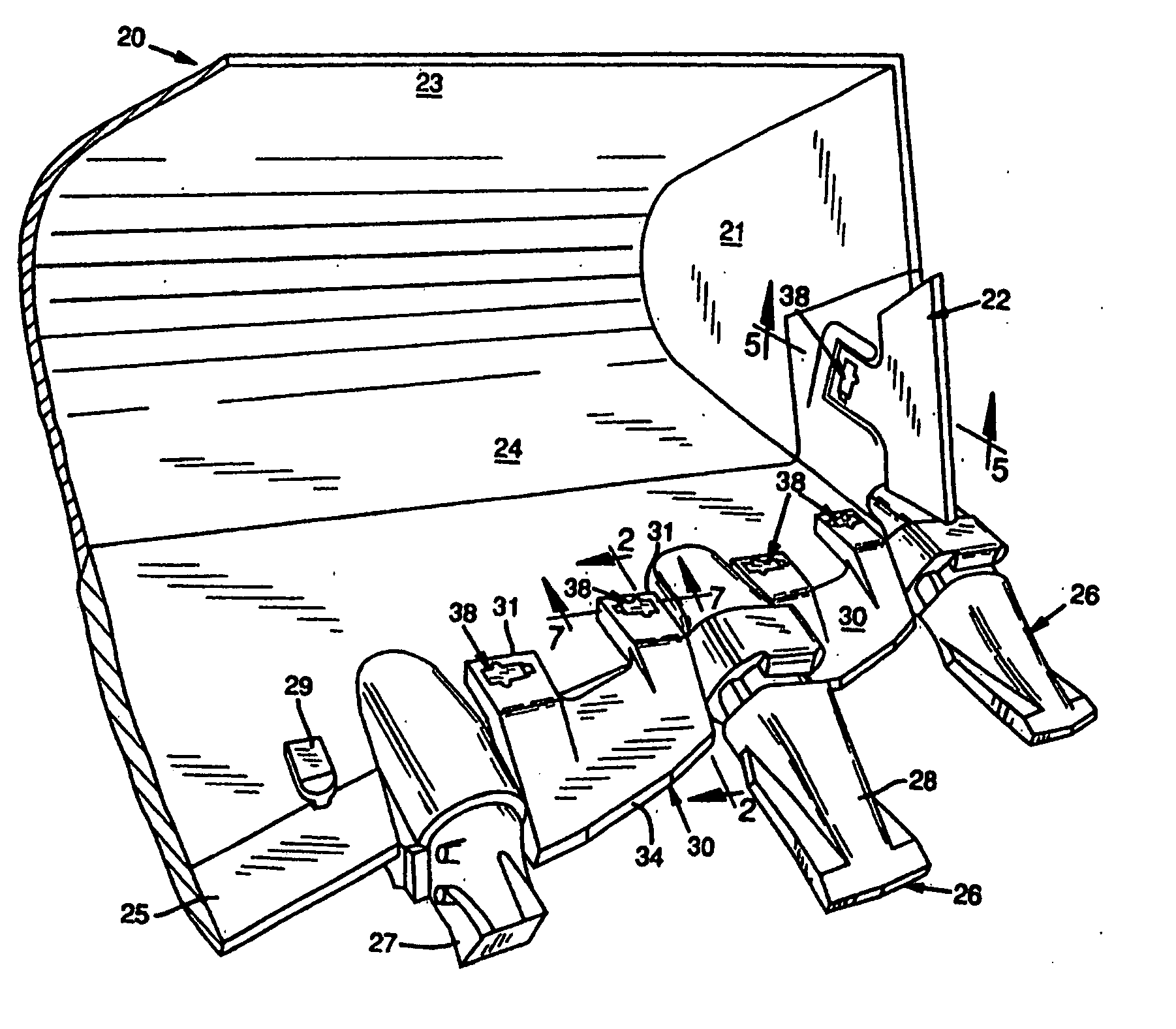
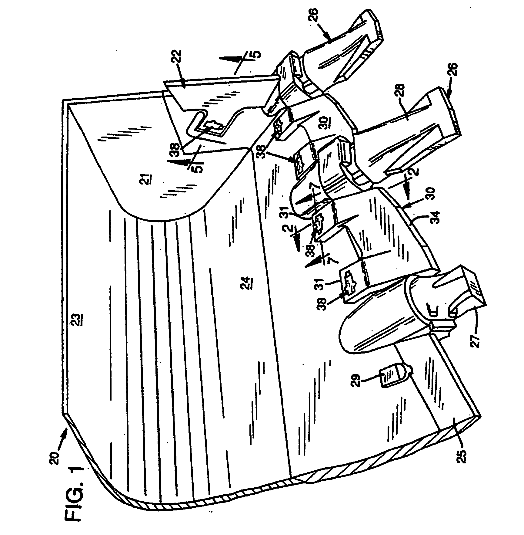
[0021] With reference to FIG. 1, numeral 20 designates generally a bucket having sidewalls or wings as at 21 equipped with a forwardly-facing protector 22, and a rear wall 23 merging into a bottom wall 24. The bottom wall 24 terminates in a forwardly positioned lip 25. The sidewalls and lip form a leading edge to the bucket. This is, of course, simply one example of an excavator which can be provided with a wear assembly in accordance with the present invention. The present invention could be used with other kinds of buckets or other digging equipment (e.g., dredge cutterheads).

[0022] The lip 25 is equipped with transversely spaced-apart excavating teeth generally designated 26 (see the lower right), each of which preferably includes an adapter 27 fixed to the lip 25 and a point or tip 28 releasably mounted on each adapter 27. The portions of the lip 25 between the teeth are protected by wear members 30 mounted to the lip through cooperation with upstanding bosses 29 (see the lower...


PUM


Abstract

A wear assembly for excavating equipment which has a wear member overlying a leading edge of the excavating equipment, a removable lock for releasably holding the wear member to the leading edge, and a stabilizer, wherein (i) the wear member has a pair of legs to straddle the leading edge with a first leg extending along a first side of the leading edge and a second leg extending along a second side of the leading edge opposite the first side, (ii) the first leg has an opening for receiving the lock and a second leg free of such locks, and (iii) the stabilizer is fixed to the second side of the leading edge and includes a holding surface to overlie a portion of the second leg to prevent the second leg from moving away from the second side of the leading edge.

Description

FIELD OF THE INVENTION [0001] This invention relates to a wear assembly and, particularly, to a replaceable assembly for protecting a leading edge or edges of a bucket or other earth engaging equipment. BACKGROUND AND SUMMARY OF THE INVENTION [0002] The invention finds utility in connection with excavating equipment, for example, along the leading edge of a dragline bucket, front end loader, face shovel, etc. In many instances the bucket may be equipped with transversely spaced excavating teeth to facilitate earth penetration. In the past, many operators have found it advantageous to protect both the bucket lip between the teeth and the bucket wings. One example of such a construction is disclosed in co-owned U.S. Pat. No. 3,621,594 marketed by ESCO Corporation of Portland, Oreg., U.S.A. under the trademark “ZIPPER LIP.” Another type of lip wear edge can be seen in co-owned U.S. Pat. No. 3,865,177. Other patents dealing with lip wear edges are U.S. Pat. Nos. 3,995,384 and 4,748,754....

Claims


Application Information

Patent Timeline
IPC IPC(8): E02F9/28
CPCE02F9/2833
Inventor MCCLANAHAN, ROBERTSTITZEL, ADAM
Owner ESCO CORP
Learn More