
Energy storage apparatus and related method

a technology of energy storage apparatus and energy density, which is applied in the direction of emergency protective arrangements for limiting excess voltage/current, transportation and packaging, and arrangements for several simultaneous batteries, etc., can solve the problems of difficult parallel charging of battery modules connected in parallel, more difficult configuration of batteries in parallel, and inferiority of ultracapacitors to batteries in terms of specific energy and energy density

Inactive Publication Date: 2006-10-05
AEROVIRONMENT INC
View PDF18 Cites 24 Cited by
  • Summary
  • Abstract
  • Description
  • Claims
  • Application Information

AI Technical Summary

Benefits of technology

The present invention relates to a device and method for controlling the voltage across an energy storage device, such as a capacitor, as electrical energy is received or delivered. The device includes a power processing unit with a switching module and a control module. The control module includes a pulse generator and a plurality of switches that are coupled to the energy storage device. The power processing unit can control the fluctuation in voltage across the energy storage device to regulate the flow of electrical energy. The technical effect of the invention is to provide a more efficient and effective way to manage the voltage across an energy storage device during power conversion.

Problems solved by technology

On the other hand, batteries are more difficult to configure in parallel, especially at the module level, due to circulating currents that are created between battery modules that are connected in parallel.
Also, it is difficult to provide balanced charging to the battery modules that are connected in parallel.
Despite these advantages, ultracapacitors are still inferior to batteries in terms of their specific energy and energy density.
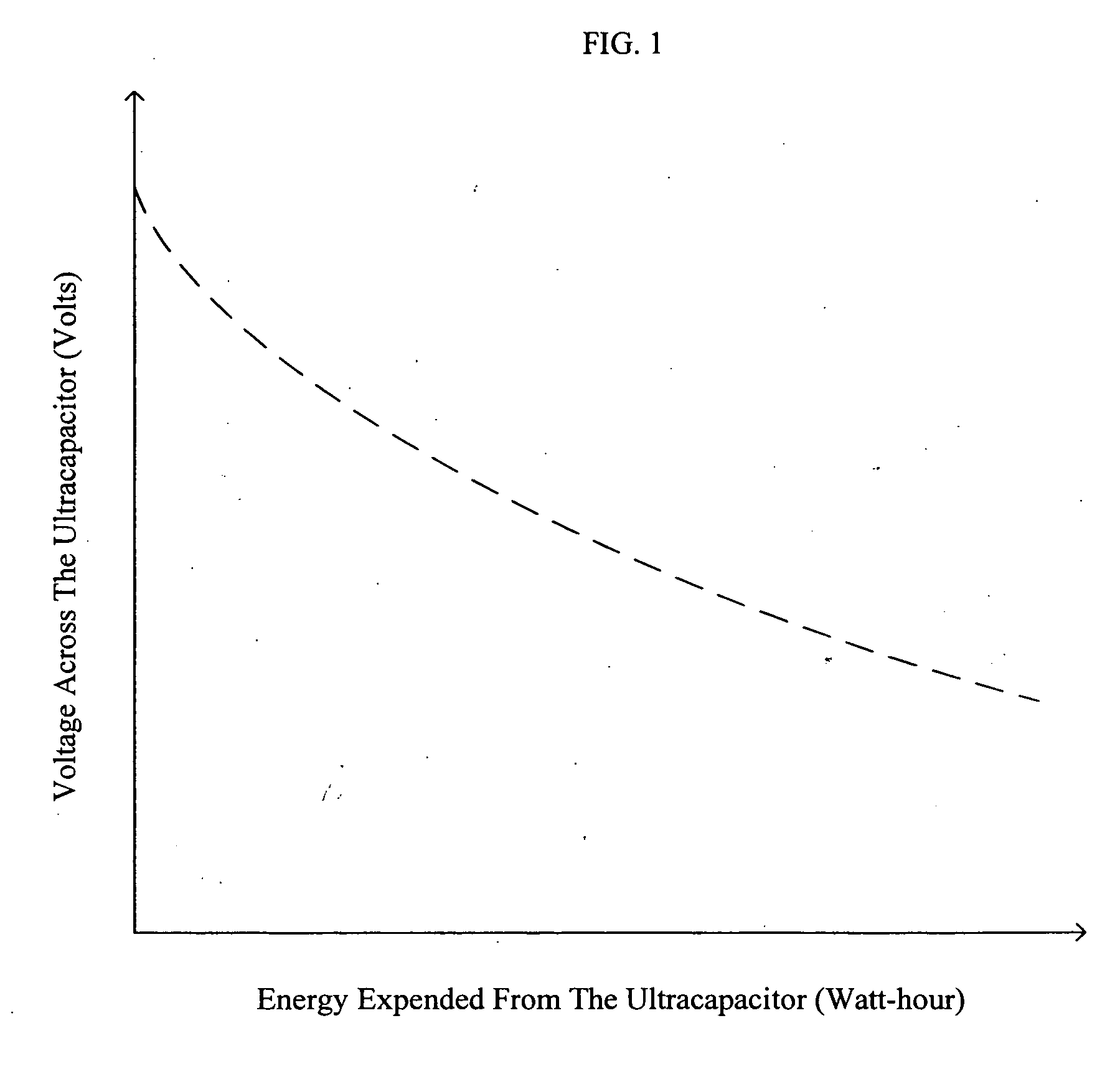
A clear limitation associated with ultracapacitors is that as the energy stored in the ultracapacitor is used, the voltage across the ultracapacitor's terminals decreases in value.
For most applications, such a fluctuation in voltage is significant and undesirable.

Method used


Image

  • Energy storage apparatus and related method
  • Energy storage apparatus and related method
  • Energy storage apparatus and related method

Examples


Embodiment Construction

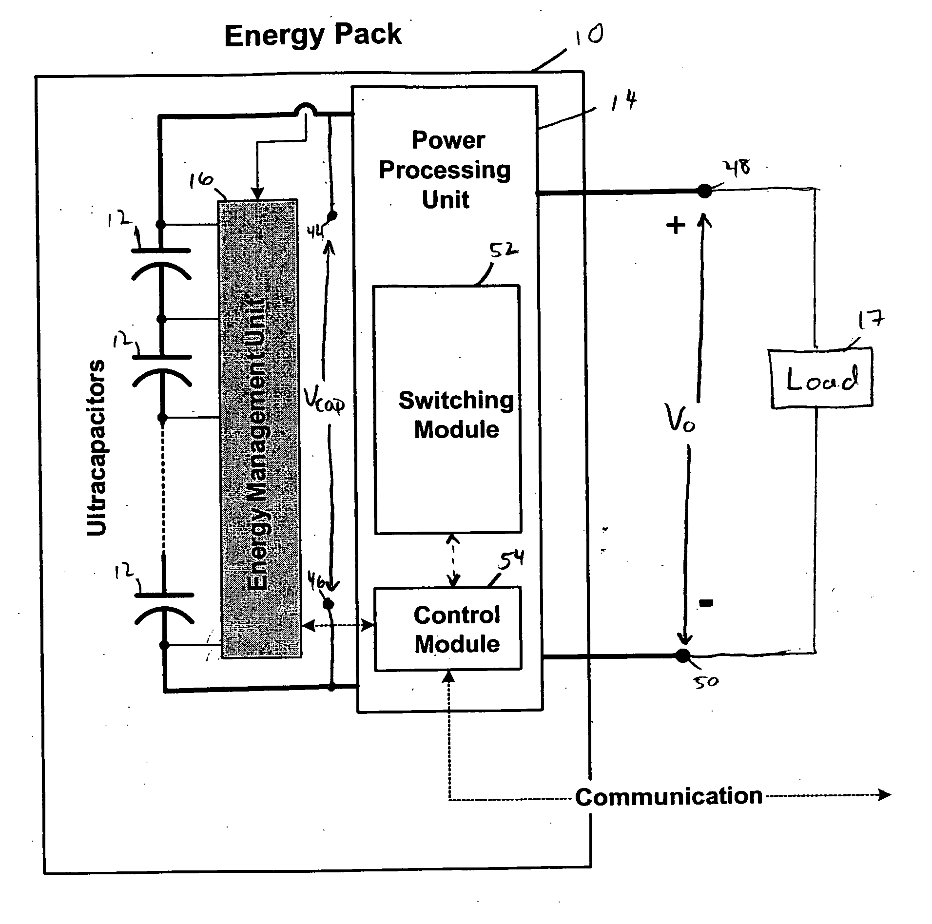
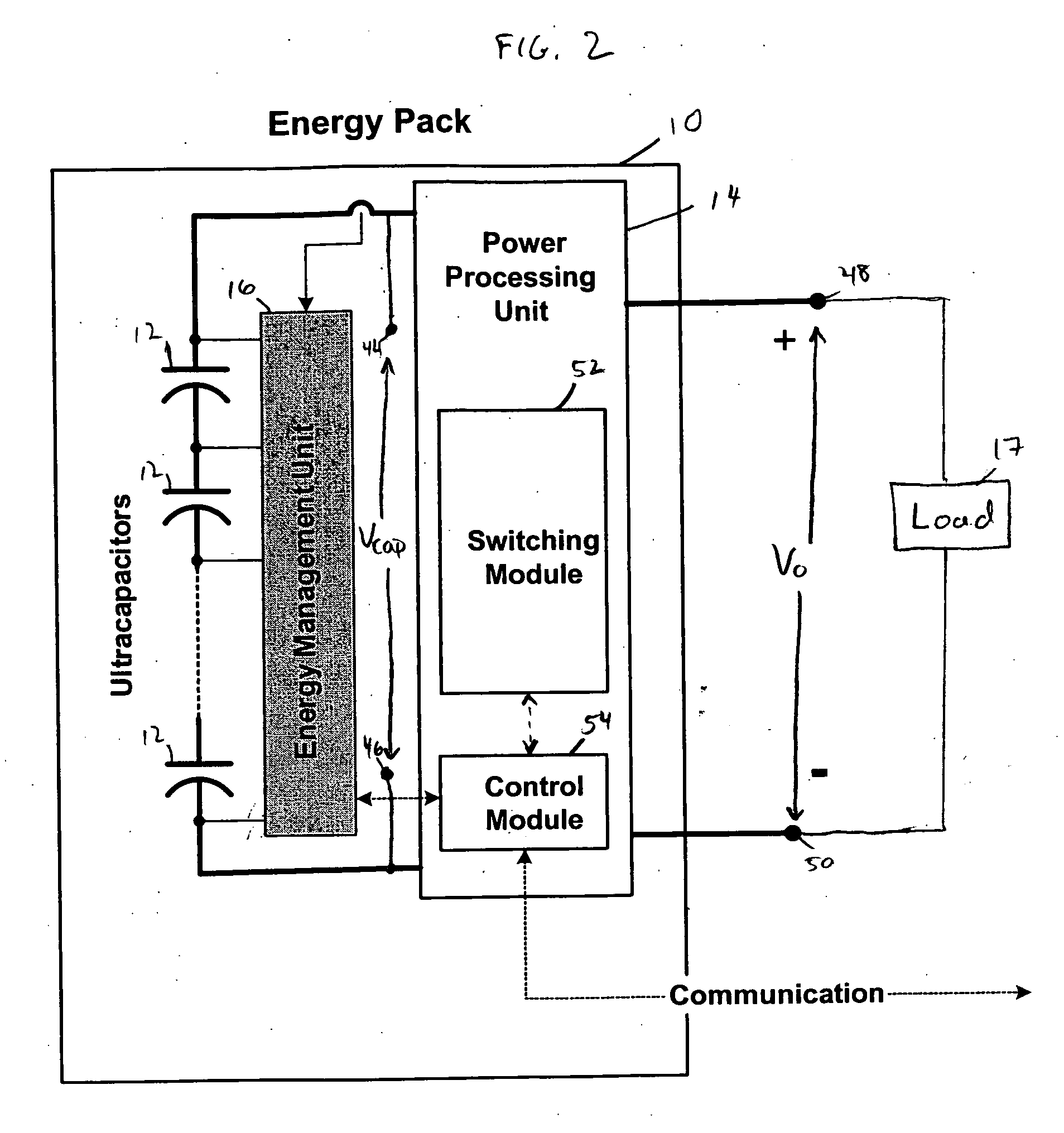
[0032] With reference now to the illustrative drawings, and particularly to FIG. 2, there is shown an energy storage device (“energy pack”) 10 that includes a plurality of serially connected ultracapacitors 12, which collectively are coupled in parallel with a high-efficiency and high-power density power processing unit (“power processing unit”) 14, and an energy management unit 16. The power processing unit, as discussed below, is configured to control a fluctuation in voltage across the power processing unit as electrical energy is delivered to the plurality of ultracapacitors, or electrical energy is output from the plurality of ultracapacitors to a load 17, or the like. While this detailed description focuses on an energy pack that includes ultracapacitors, one having ordinary, skill in the art will recognize that other types of energy storage devices that are configured to store electrical energy, for example, capacitors other than ultracapacitors, e.g., electrostatic capacitor...


PUM


Abstract

An apparatus including an energy storage device and a power processing unit that is coupled to the energy storage device. The energy storage device is configured to deliver electrical energy to a load. The energy storage device also is configured to receive electrical energy from a source. The power processing unit is configured to control a fluctuation in voltage across the energy storage device while electrical energy is received by the energy storage device, or while electrical energy is delivered from the energy storage device to the load.

Description

BACKGROUND OF THE INVENTION [0001] 1. Field of the Invention [0002] The invention relates generally to the field of energy storage. More specifically, the invention relates to an energy storage apparatus for storing electrical energy. [0003] 2. Description of the Related Art [0004] Recently, ultracapacitors have become popular for the storage of electrical energy, because ultracapacitors can provide high levels of capacitance, e.g., 3,000 farads (“F”), with high output current, e.g., 500 Amperes. These high levels of capacitance are facilitated by the small spacing between the electrodes of the ultracapacitor, which can be less than a few nanometers. [0005] When compared with electrochemical storage devices, i.e., batteries, ultracapacitors offer significant advantages. For example, ultracapacitors can provide ten to thirty times the cycle life of batteries. Also, ultracapacitors require less maintenance than batteries, are more efficient than batteries, and are easier to manufactur...

Claims


Application Information

Patent Timeline
Patent Type & Authority Applications(United States)
IPC IPC(8): H02H7/00
CPCH02J7/0016H02M3/1582H02J7/345
Inventor DABOUSSI, ZAHER
Owner AEROVIRONMENT INC
Learn More