Compact diversity antenna
a technology of antennas and antenna supports, applied in the direction of antennas, antenna supports/mountings, radiating element structural forms, etc., can solve the problems of increasing the complexity and variety of advanced functions and services that the terminals are capable of performing, and adding to the volume and weight of the terminal
- Summary
- Abstract
- Description
- Claims
- Application Information
AI Technical Summary
Problems solved by technology
Method used
Image
Examples
first embodiment
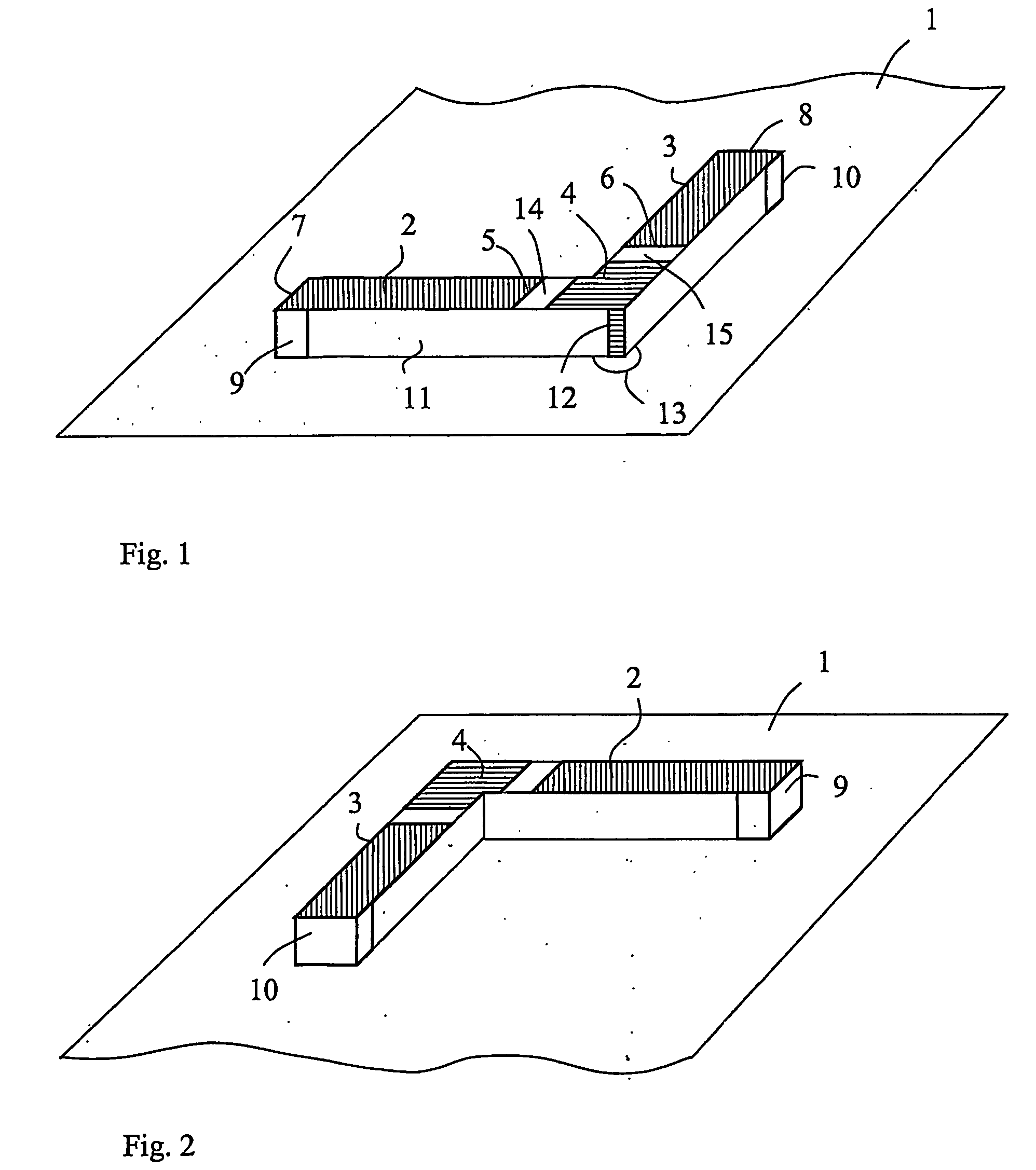
[0031]FIG. 1 schematically illustrates a compact diversity radio antenna according to the present invention, and FIG. 2 illustrates the same 30 embodiment as seen from an opposite angle. The antenna is carried on a support structure, such as a printed circuit board, PCB, preferably defining a substantially plane support surface. The support structure includes an electrical ground substrate 1, which may cover a major portion of the support structure. Alternatively, the ground substrate 1 may be confined to a portion of the support structure, over which portion the antenna is placed. The ground substrate 1 is preferably realised as a 5 material layer on an outer side or an intermediate layer of a PCB. In another embodiment, the ground substrate may be formed directly on a bottom side of the antenna. In FIG. 1, the ground substrate 1 is illustrated as a flat substrate extending beyond the antenna.
[0032] The antenna is placed on or adjacent to the ground substrate 1, and comprises 10 a ...
second embodiment
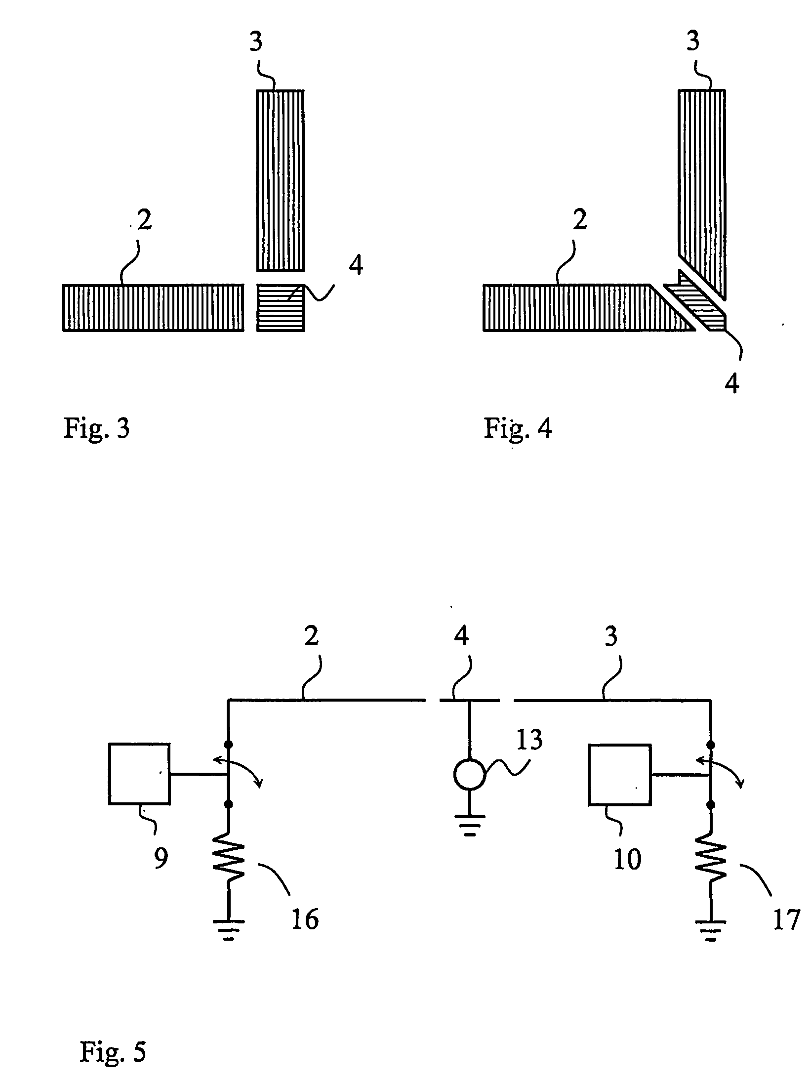
[0035]FIG. 3 illustrates a second embodiment, only showing the antenna elements 2,3 and excitation electrode 4. In this example, excitation electrode 4 is rectangular, or even quadratic, and therefore does not extend into the legs of the first surface of dielectric member 11.
[0036]FIG. 4 illustrates a third exemplary embodiment, in which excitation electrode 4 extends substantially diagonally over the intersection of the legs of the dielectric member 11. Also the first ends 5 and, respectively, of the antenna elements 2,3 are angled such that the gaps 14,15 have constant widths. Other specific embodiments of the pattern of the antenna structure are of course possible, and the antenna elements may e.g. be meandered in their extension between the respective first ends 5,6 and second ends 7,8.
[0037] The antenna elements 2,3 are selectively connected to ground substrate 1, by means of ground connector switch means 9,10. The ground connector switch means 9,10 are preferably devised to c...
PUM
 Abstract
Description
Claims
Application Information
 - R&D
- Intellectual Property
- Life Sciences
- Materials
- Tech Scout
- Unparalleled Data Quality
- Higher Quality Content
- 60% Fewer Hallucinations
Browse by: Latest US Patents, China's latest patents, Technical Efficacy Thesaurus, Application Domain, Technology Topic, Popular Technical Reports.
© 2025 PatSnap. All rights reserved.Legal|Privacy policy|Modern Slavery Act Transparency Statement|Sitemap|About US| Contact US: help@patsnap.com


