Air compression internal combustion engine

a technology of internal combustion engine and air compression, which is applied in the direction of machines/engines, mechanical devices, cylinders, etc., can solve the problems poor throughflow values, and achieve the effects of large clearance volumes in the combustion chamber, small valve lift, and large valve li

Inactive Publication Date: 2006-10-05
DAIMLER AG
View PDF10 Cites 0 Cited by
  • Summary
  • Abstract
  • Description
  • Claims
  • Application Information

AI Technical Summary

Benefits of technology

[0008] The design parameters constitute a balanced compromise with regard to obtaining both optimum swirl and throughflow characteristic values and also permissible mechanical loads. The design parameters are also suitable for optimizing the valve projection, that is to say, the lift of sections of the valve heads into the combustion chamber. As a result, both, an excessively large valve lift which requires excessively large valve accommodation recesses in the piston base and adversely affects combustion, and an excessively small valve lift, which results in large clearance volumes in the combustion chamber and poor throughflow values, are avoided. Finally, the design parameters provide for a favorable distance of the individual gas exchange valves from the cylinder wall so that disadvantages in swirl and throughflow behavior are avoided.

Problems solved by technology

As a result, both, an excessively large valve lift which requires excessively large valve accommodation recesses in the piston base and adversely affects combustion, and an excessively small valve lift, which results in large clearance volumes in the combustion chamber and poor throughflow values, are avoided.

Method used


Image

  • Air compression internal combustion engine
  • Air compression internal combustion engine
  • Air compression internal combustion engine

Examples


Embodiment Construction

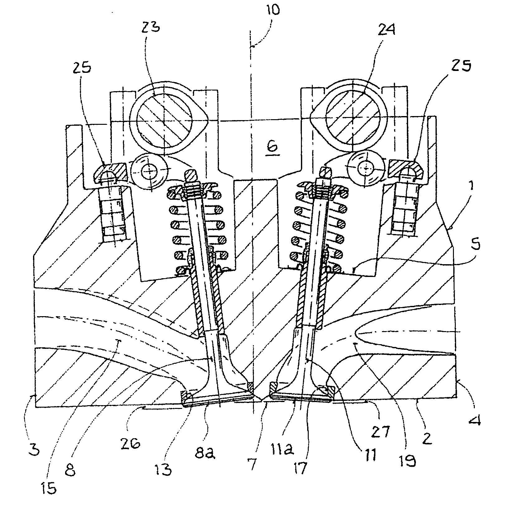
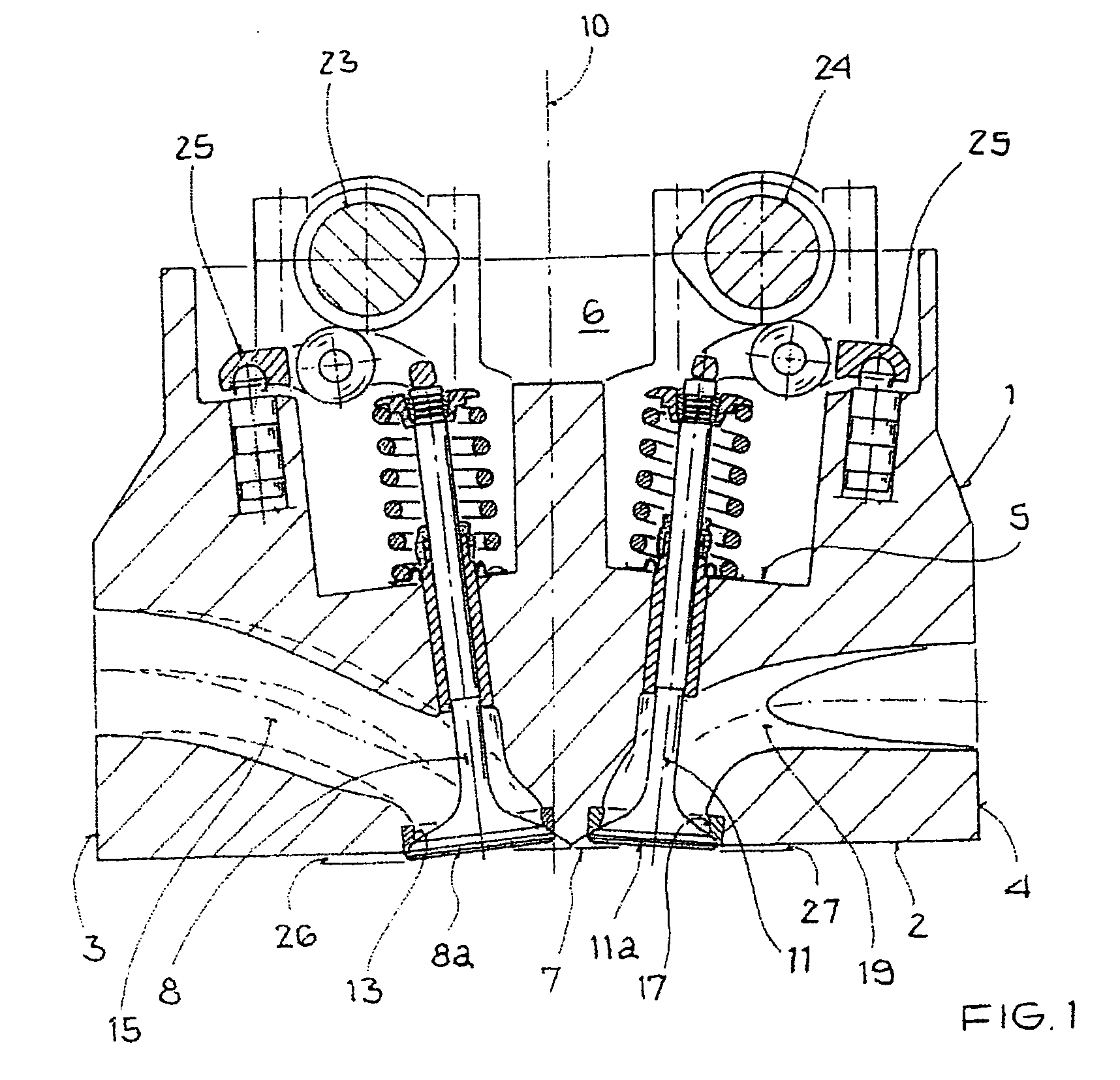
[0012] In the figures a cylinder head housing for a multi-cylinder air compression internal combustion engine is denoted by 1. The cylinder head housing 1 is delimited by a cylinder head bottom face 2, two side walls 3, 4 and a top face 5, in which a control space 6 for holding a valve train is provided.

[0013] Part of the cylinder head bottom face 2 forms a combustion chamber section 7 which covers a cylinder in an engine block (not illustrated). In FIG. 2, the combustion chamber section 7 is shown delimited by a circle which corresponds to the cylinder diameter “Dcylinder”. The internal combustion engine has four gas exchange valves per cylinder, which gas exchange valves are arranged within the combustion chamber section 7 in such a way that the two intake valves 8 and 9 are positioned to the left of a vertical cylinder head longitudinal central plane 10 and the two exhaust valves 11 and 12 are positioned to the right of the latter. The intake valves 8 and 9 control, by means of ...


PUM


Abstract

In an air compression internal combustion engine having at least one cylinder, a combustion chamber formed in the cylinder and delimited at its longitudinal ends by a piston and a cylinder head which covers the cylinder, two intake valves and two exhaust valves per cylinder are installed in the cylinder head so as to be inclined at a valve angle α and β, respectively, in the range of 2° to 9° relative to a cylinder head longitudinal central plane (10), the valves each have a valve diameter Dintake and Dexhaust which is 30% to 40% of the cylinder diameter Dcylinder, the valve heads are disposed at a distance from the cylinder wall which delimits the combustion chamber, and webs of a predefined width are provided between adjacent valves of a cylinder, and the valve heads have sections which protrude into the combustion by a predetermined limited amount.

Description

[0001] This is a Continuation-In-Part Application of International Application PCT / EP2004 / 010050 filed Sep. 9, 2004 and claiming the priority of German Application 103 49 889.7 filed Oct. 9, 2003.BACKGROUND OF THE INVENTION [0002] The invention relates to an air compression internal combustion engine having at least one cylinder arranged in an engine block, a combustion chamber which is formed in the cylinder and is delimited at its longitudinal ends by a piston and a cylinder head which covers the engine block. There are four gas exchange valves per cylinder which are in each case installed in the cylinder head so as to be inclined at a valve angle in the range from 2° to 9° relative to a cylinder head longitudinal central plane. The gas exchange valves each have a valve diameter which is 30% to 40% of the cylinder diameter, and the valve heads, which are situated in the base of the cylinder head, also are disposed at a distance from the cylinder walls. [0003] An air compression in...

Claims


Application Information

Patent Timeline
Patent Type & Authority Applications(United States)
IPC IPC(8): F02B75/02F02B15/00F02F1/42F01L3/06F01L3/22F01L35/04F02B3/06F02B31/00F02F1/24
CPCF01L3/06F01L3/22F01L35/04F01L2001/0537F01L2105/02Y02T10/146F02B2031/006F02B2275/14F02B2275/18F02F2001/245F02B3/06F01L2305/02Y02T10/12
Inventor ASTNER, JOSEFENGEL, ULRICHJUTZ, BERNHARDZINK, EDWIN
Owner DAIMLER AG
Why Eureka
Try Eureka