Translational hinged door plate system
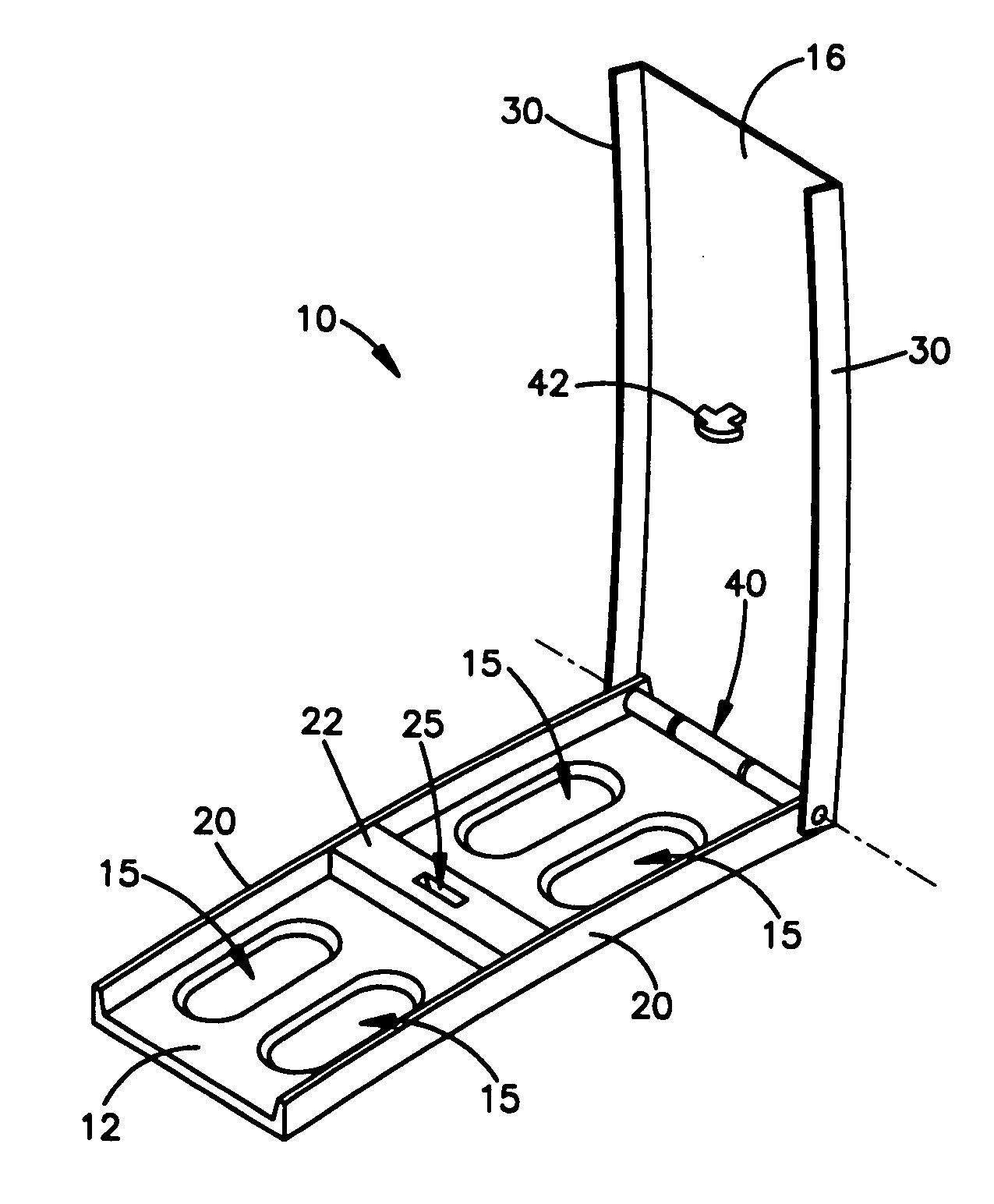
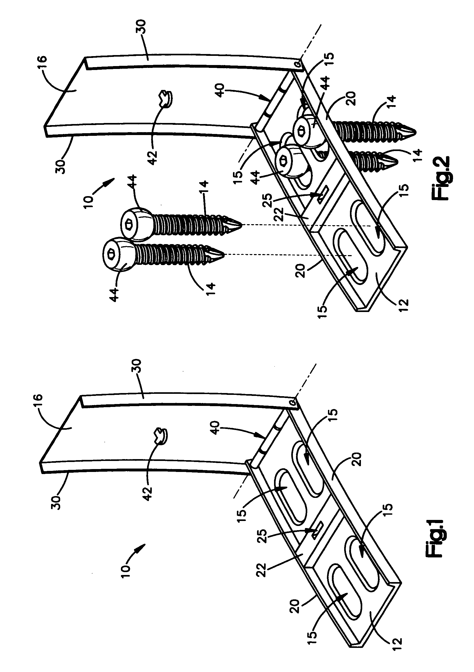
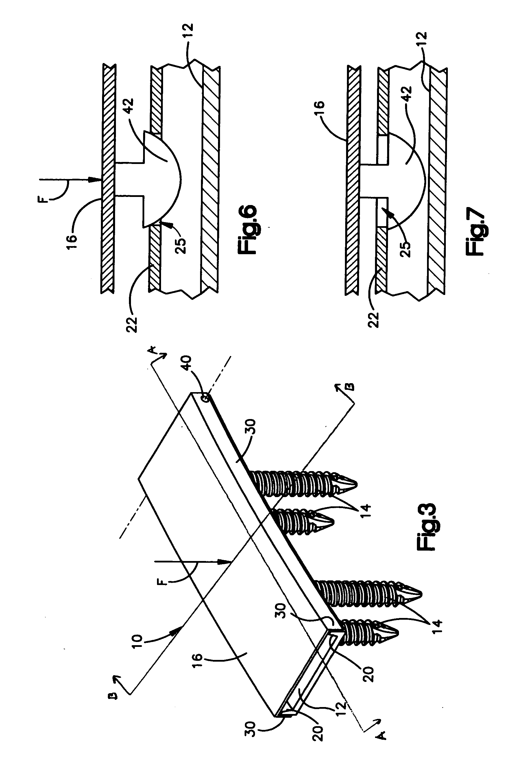
a technology of hinged door plate and translation plate, which is applied in the field of fixing system, can solve the problems of increasing the attachment alternative of the fastener, subsidence may tend to shift more spinal load to the plate than the spinal load, and affecting the stability of the plate, so as to prevent the back-out of the bone fastener
- Summary
- Abstract
- Description
- Claims
- Application Information
AI Technical Summary
Benefits of technology
Problems solved by technology
Method used
Image
Examples
second embodiment
[0050]FIGS. 8-9 show a one-level bone fixation assembly 100. The fixation assembly 100 in this embodiment includes a bone fixation plate 112 with slots 115 configured to receive fasteners 116 in installed positions in which the outer end portions 118 of the fasteners 116 are located within the slots 115. The fixation assembly 100 may further include a fastener retainer device in the form of a cover plate 120 which, like the cover plate 16 described above, may be supported by a hinge 122 for movement pivotally into a closed position on the fixation plate 112. When the cover plate 120 is in the closed position, as shown in FIG. 8, it may extend over the locations taken by the outer end portions 118 of the fasteners 116 in the slots 115 to block the fasteners 116 from backing out of their installed positions on the fixation plate 112. However, the assembly 100 differs from the previously recited assembly 10 by including a locking device 130 as a substitute for the closure block 22 and ...
third embodiment
[0052]FIGS. 10-12 show a one-level bone fixation assembly 200. In this embodiment, assembly 200 includes a pair of bone fixation plates 210 and 212. The fixation plates 210 and 212 may be joined by a connector 214 to define a single spinal fixation plate 216 with two pairs of fastener slots 217 and 219. Two fastener retainer devices 220 and 222 may be mounted on the fixation devices 210 and 212 by hinges 224 and 226, respectively, that may support them for movement pivotally into closed positions.
[0053] As shown in the embodiment of FIGS. 11 and 12, the retainer device 220 may be a cover plate with an arcuate peripheral edge portion 230 that may snap into interlocked engagement with a lip 232 at the peripheral edge of the fixation device 210. This may occur upon pivotal movement of the retainer device 220 from the partially closed position of FIG. 11 to the closed position of FIG. 12 under an applied force F. When the retainer device 220 is in the closed position, it may extend over...
fourth embodiment
[0054]FIG. 13 is a one-level bone fixation assembly 300 similar to the assembly 200 of FIGS. 10-12. The fastener retainer device 302 in this assembly 300 may have two arcuate peripheral edge portions 306, whereas the fastener retainer device 220 described above in connection with FIGS. 10-12 has a hinge 224 and a single arcuate peripheral edge portion 230. The assembly 300 may further include a bone fixation plate 310 with two corresponding lips 312, each of which may be substantially the same as the single lip 232 of FIGS. 10-11.
[0055] The retainer device 302 of FIG. 13 can be snapped into interlocked engagement with the fixation plate 310 in at least two different ways. An edge portion 306 at one side of the device 302 can first be hooked over the corresponding lip 312, and the other edge portion 306 can then be snapped pivotally over its corresponding lip 312, similar to the manner described above with reference to FIGS. 11-12. Alternatively, the retainer device 302 can first be ...
PUM
 Abstract
Description
Claims
Application Information
 - R&D
- Intellectual Property
- Life Sciences
- Materials
- Tech Scout
- Unparalleled Data Quality
- Higher Quality Content
- 60% Fewer Hallucinations
Browse by: Latest US Patents, China's latest patents, Technical Efficacy Thesaurus, Application Domain, Technology Topic, Popular Technical Reports.
© 2025 PatSnap. All rights reserved.Legal|Privacy policy|Modern Slavery Act Transparency Statement|Sitemap|About US| Contact US: help@patsnap.com


