
Method and apparatus for finding a mobile radio terminal

a mobile radio terminal and mobile technology, applied in the direction of supervision/control auxiliaries, instruments, navigation instruments, etc., can solve the problems of inability to consider a useful homing system, random errors in the initial angle of arrival measurement, and poor performan

Inactive Publication Date: 2006-09-28
SEEKER WIRELESS PTY LTD
View PDF4 Cites 68 Cited by
  • Summary
  • Abstract
  • Description
  • Claims
  • Application Information

AI Technical Summary

Benefits of technology

[0159] The present invention has significant advantages to the existing ways of homing in on mobile terminals.

Problems solved by technology

As with all radio signal measurements, the initial angle of arrival measurement will exhibit random errors.
If the error in the position estimate is large, then the elaborated location system may not provide a method of actually finding the target device with any degree of certainty, and therefore cannot be considered to be a useful homing system.
In particular areas, for example downtown, the performance could be much worse.
It can be seen however that the accuracy requirements in the mandate do not provide the basis for a highly reliable homing capability.
In an urban area, 300 metres is simply not sufficient to find a lost object or person, especially in an emergency when time is of the essence.
Even the accuracy requirements for a self-positioning system fall short of the accuracy needed for an effective homing capability.
The accuracy requirements in the FCC mandate, inadequate as they are for homing, reflect the current limits of technical feasibility for commercial, widely deployable, mobile telephone location systems.
This bias translates into errors in the position estimate.
The near-far interference and signal obscuration on the other hand result in a smaller number of transmitters being detected by the mobile in a self-positioning system (or a fewer number of receivers detecting the signals transmitted by the mobile in a remote-positioning system).
The detection of fewer signals means fewer observations available for determining the location and a corresponding degradation in the accuracy.
In practice however the rate of error reduction with this type of averaging may be at best slow due to persistent biases.

Method used


Image

  • Method and apparatus for finding a mobile radio terminal
  • Method and apparatus for finding a mobile radio terminal
  • Method and apparatus for finding a mobile radio terminal

Examples


Embodiment Construction

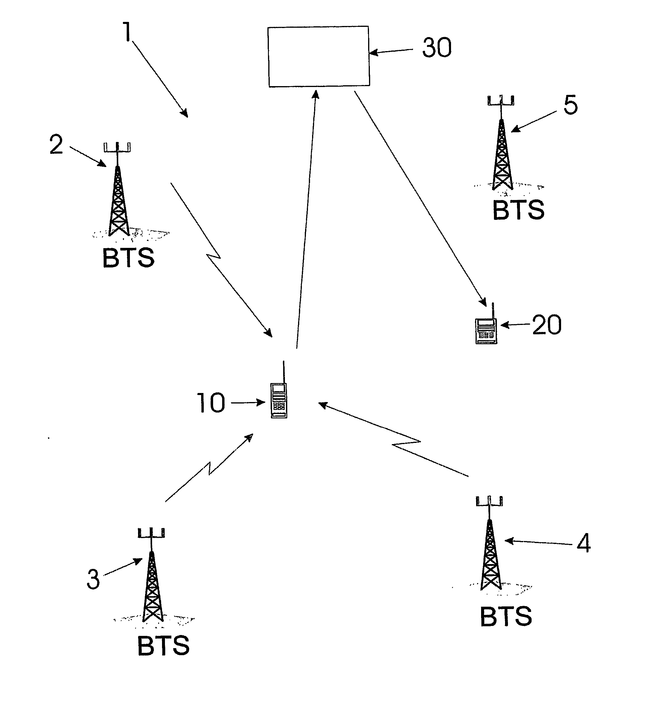
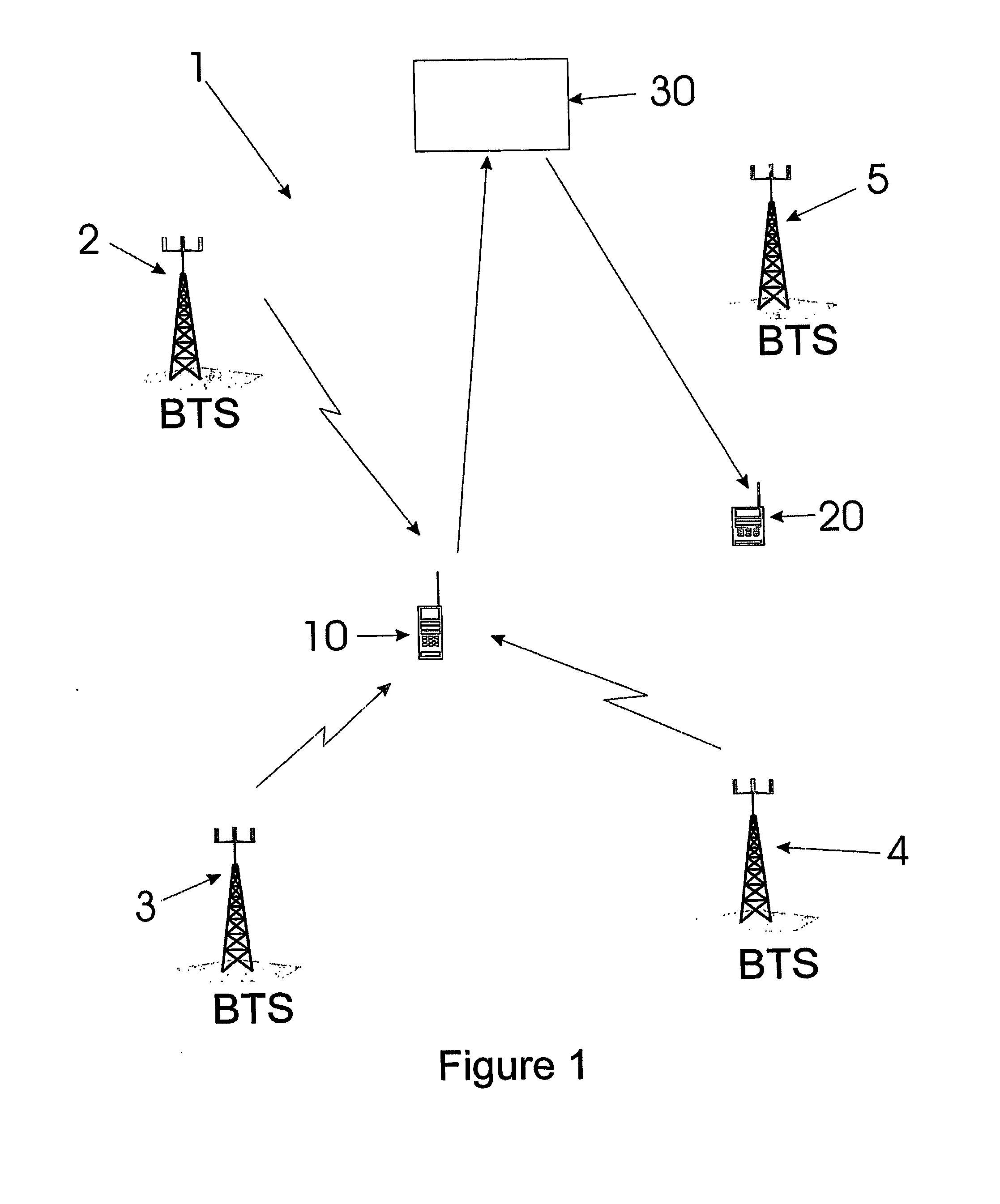
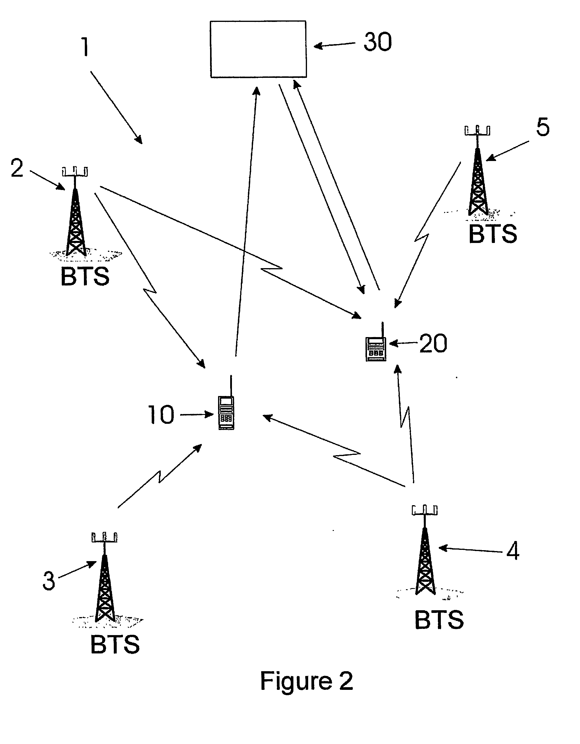
[0043] In the following description, the homing system refers to the combination of the processing means for estimating relative position, selecting search routes, etc. and the homing device. The homing device refers to the device carried by the user through which the system communicates with the user. On occasions, the term “seeker” may be used, which may refer to the homing device itself or a User of the homing device, or the combination of the User and the homing device.

[0044] In the following paragraphs a series of methods are disclosed which can be used to implement an effective system for homing in on a mobile radio terminal. These methods can be applied in different combinations depending on the nature of the application and the technical and economic constraints that affect that application. To aid in understanding the different methods and the circumstances under which they could be used, the possible homing applications are arranged into three groups according to the capa...


PUM


Abstract

A method and apparatus for finding a radio terminal (10) in a radio communications network. The method includes making observations of attributes of radio signals associated with the radio terminal (10) and generating a route for a seeker (20) to find the radio terminal (10), based on the observations and estimated error distributions of those observations. The route may be displayed over a topographical map to guide the seeker to the target.

Description

FIELD OF THE INVENTION [0001] The invention relates to systems or methods for finding a mobile radio terminal. BACKGROUND OF THE INVENTION [0002] In the past, many attempts have been made to develop methods of determining the position of a target in a given area. Such applications include determining the location of a military target to direct weaponry to that target, determining the location of a vehicle which has been stolen to enable it to be retrieved and determining the position of a person who has become lost in for example, a wilderness setting. [0003] A vital distinction is maintained throughout the following between on the one hand, the process of locating a mobile radio terminal and on the other hand the process which will be referred to as finding the mobile terminal. In the literature, locating a mobile terminal refers to the process whereby an estimate is made of the position of the mobile terminal. That process is affected by a variety of random errors and therefore th...

Claims


Application Information

Patent Timeline
Patent Type & Authority Applications(United States)
IPC IPC(8): H04Q7/20G01C21/34G01S5/00G01S5/02G01S19/09G01S19/46H04M7/06H04W64/00
CPCG01C21/362G01S5/0045G01S5/02G01S5/0221H04W64/00
Inventor DRANE, CHRISTOPHER RIDGWAYMACNAUGHTAN, MALCOLM DAVID
Owner SEEKER WIRELESS PTY LTD
Learn More