
Method and apparatus for total disc replacements with oblique keels

a total disc and oblique technology, applied in the field of artificial disc replacements, can solve the problems of reduced efficiency of disc degeneration surgery treatment, reduced treatment effect of disc degeneration surgery, and reduced ability to control vertebral motion, so as to reduce the risk of injuring the great vessels

Inactive Publication Date: 2006-09-21
FERREE BRET
View PDF19 Cites 33 Cited by
  • Summary
  • Abstract
  • Description
  • Claims
  • Application Information

AI Technical Summary

Benefits of technology

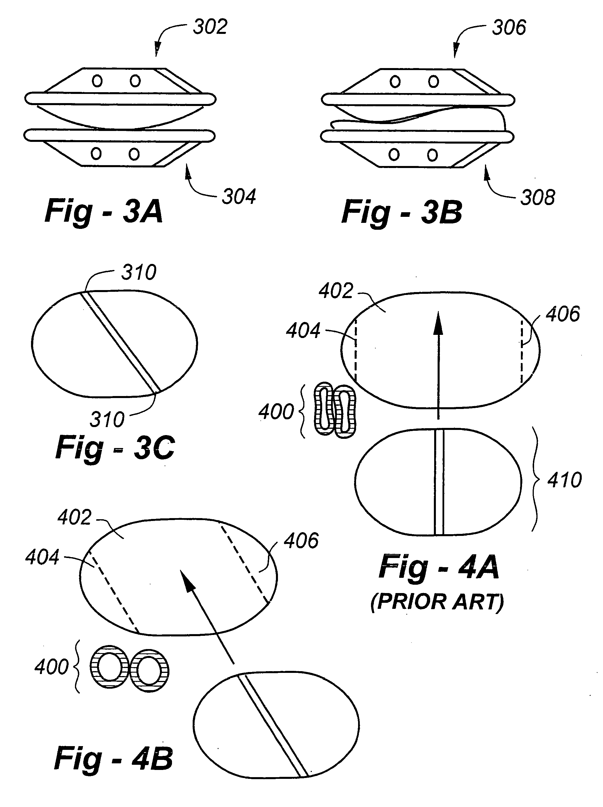
"This patent is about improving artificial disc replacement (ADR) systems by using components with non-symmetrical keels that can be inserted in an oblique direction. This reduces the need for retraction of the great vessels during insertion. Navigational systems can be used to help align the components with the oblique-oriented keels. The ADR system also includes guides for aligning the ADR and cutting an oblique slot into the vertebral endplate to receive the keel. A screw adapted to penetrate a vertebral body may be used in conjunction with the keel. The invention allows for a second ADR to be installed at a different level with a different orientation of the keel. The non-symmetrical endplate also decreases the risk of injuring the great vessels."

Problems solved by technology

The nucleus becomes thinner and less able to handle compression loads.
The redundant annular fibers are less effective in controlling vertebral motion.
Current surgical treatments of disc degeneration are destructive.
These destructive procedures lead to acceleration of disc degeneration.
The first two groups of procedures compromise the treated disc.
The additional stress results in premature disc degeneration of the adjacent discs.
Retraction of the great vessels is difficult and dangerous.
The danger increases the further the vessels are retracted.

Method used


Image

  • Method and apparatus for total disc replacements with oblique keels
  • Method and apparatus for total disc replacements with oblique keels
  • Method and apparatus for total disc replacements with oblique keels

Examples


Embodiment Construction

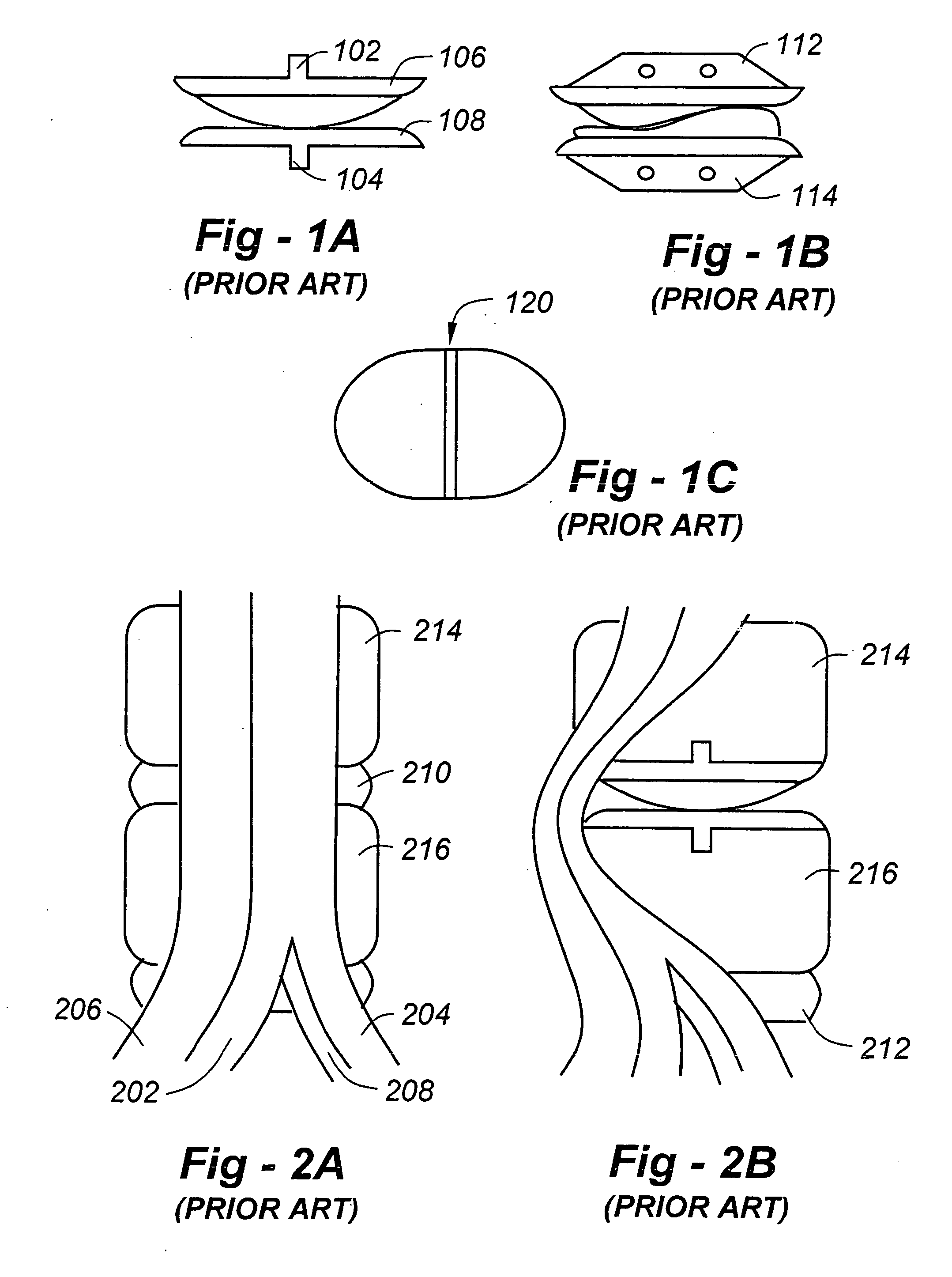
[0078]FIG. 1A is a view of the anterior aspect of a prior-art ADR. The anterior-to-posterior (A-P) oriented keels 102, 104 are represented by the projections from the top and bottom ADR endplates 106, 108. FIG. 1B is a view of the side of a prior-art ADR with anterior to posterior oriented keels 112, 114. The keels are represented by the trapezoidal shaped projections from the top and bottom ADR endplates. FIG. 1C is a view of the vertebral side of a prior-art ADR endplate. The keel is represented by area 120 of the drawing that courses from the top (posterior aspect of the ADR) to the bottom (anterior aspect of the ADR) of the drawing.

[0079]FIG. 2A is a view of the anterior aspect of the lumbar spine and the great vessels overlying the spine. The aorta and iliac arteries are indicated at 202, 204, and the vena cava and iliac veins are indicated at 206, 208. Intervertebral discs are shown at 210, 212, and vertebrae are shown at 214, 216. FIG. 2B is a view of the anterior aspect of ...


PUM


Abstract

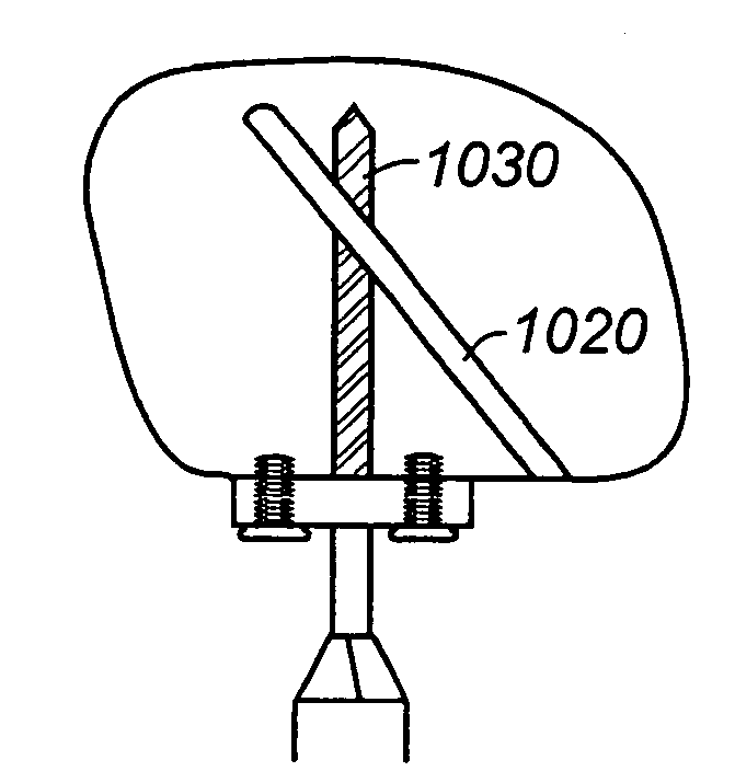
Artificial disc replacement (ADR) systems with intradiscal components feature non anterior-posterior (A-P) or oblique-oriented keels such that the great vessels do not require as much retraction during insertion. The system may further include guides for aligning the ADR prior to insertion, and for cutting an oblique slot into a vertebral endplate to receive the keel. A screw adapted to penetrate a vertebral body may be used in conjunction with the keel. The screw and keel may converge, diverge or intersect. The screw may further include a mechanism providing a locking relationship with the keel. The system may further including a guide to direct drill bits and screws through holes in the keel. ADRs according to the invention may additionally, independently include a non-symmetrical endplate shaped so as to decrease the risk of injuring the great vessels. By virtue of the invention, a second ADR may be installed at a second level having a keel oriented differently from that of the ADR having an orientation other than anterior-to-posterior.

Description

REFERENCE TO RELATED APPLICATION [0001] This application claims priority from U.S. Provisional Patent Application Ser. No. 60 / 476,522, filed Jun. 6, 2003, the entire content of which is incorporated herein by reference.FIELD OF THE INVENTION [0002] This invention relates generally to artificial disc replacements (ADRs) and, in particular, to ADRs with oblique keels. BACKGROUND OF THE INVENTION [0003] Eighty-five percent of the population will experience low back pain at some point. Fortunately, the majority of people recover from their back pain with a combination of benign neglect, rest, exercise, medication, physical therapy, or chiropractic care. A small percent of the population will suffer chronic low back pain. The cost of treatment of patients with spinal disorders plus the patient's lost productivity is estimated at 25 to 100 billion dollars annually. [0004] Seven cervical (neck), 12 thoracic, and 5 lumbar (low back) vertebrae form the normal human spine. Intervertebral disc...

Claims


Application Information

Patent Timeline
Patent Type & Authority Applications(United States)
IPC IPC(8): A61F2/44A61B17/15A61B17/16A61B17/17A61B17/80A61B17/86A61B19/00A61F2/00A61F2/30A61F2/46
CPCA61B17/15A61B17/1671A61B17/1757A61B17/8038A61B17/8605A61B2017/1602A61B2019/304A61F2/442A61F2/4425A61F2/4611A61F2002/3008A61F2002/30485A61F2002/30497A61F2002/30578A61F2002/30878A61F2002/30884A61F2002/449A61F2002/4629A61F2220/0025A61F2250/0098A61F2002/30495A61B2090/034
Inventor FERREE, BRET
Owner FERREE BRET
Learn More