
Implantable bladder sensor

a sensor and implantable technology, applied in the field of implantable bladder sensors, can solve the problems of faecal incontinence and no well-accepted medical treatment, and achieve the effects of increasing the impedance of conductive materials, reducing the cross-sectional area, and increasing volum

Inactive Publication Date: 2006-09-21
NEOPRAXIS
View PDF49 Cites 44 Cited by
  • Summary
  • Abstract
  • Description
  • Claims
  • Application Information

AI Technical Summary

Benefits of technology

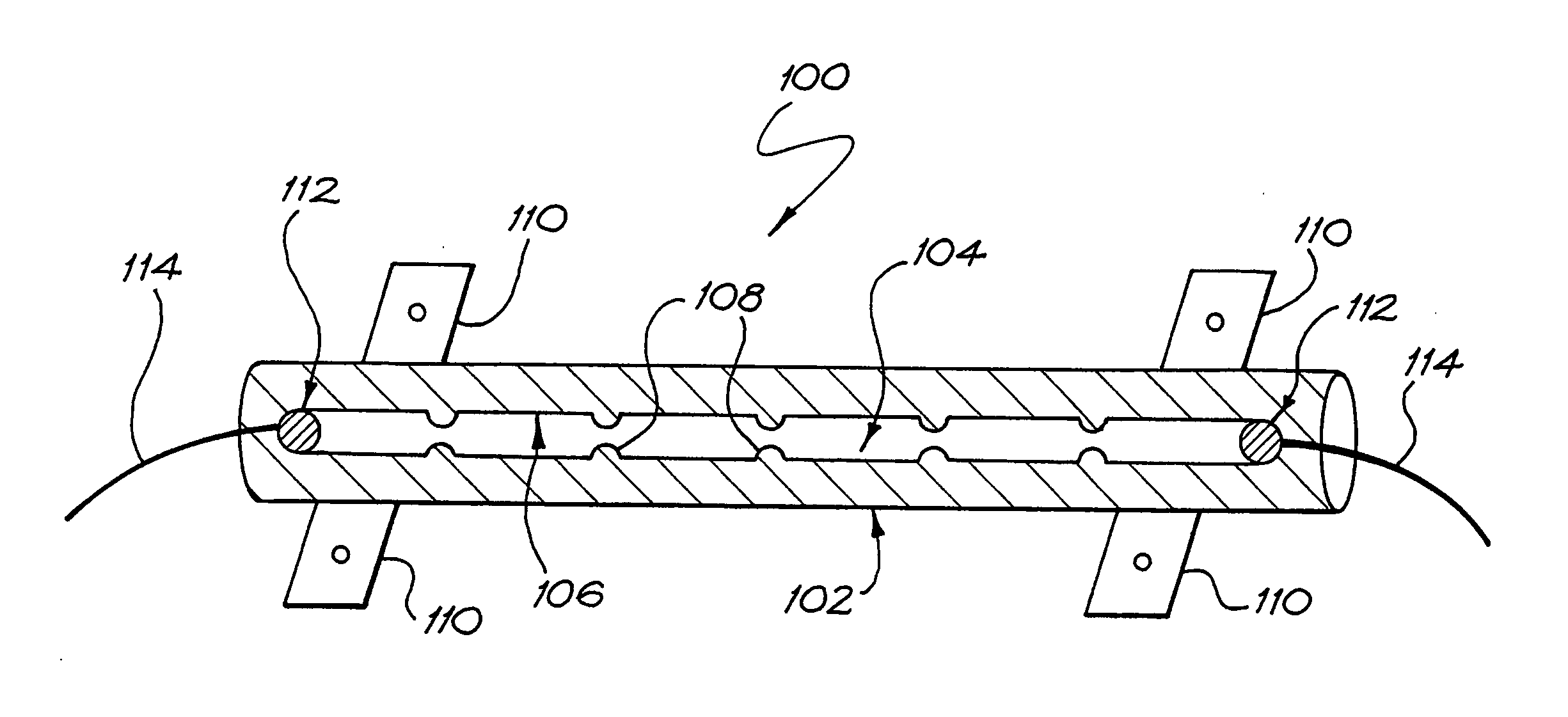
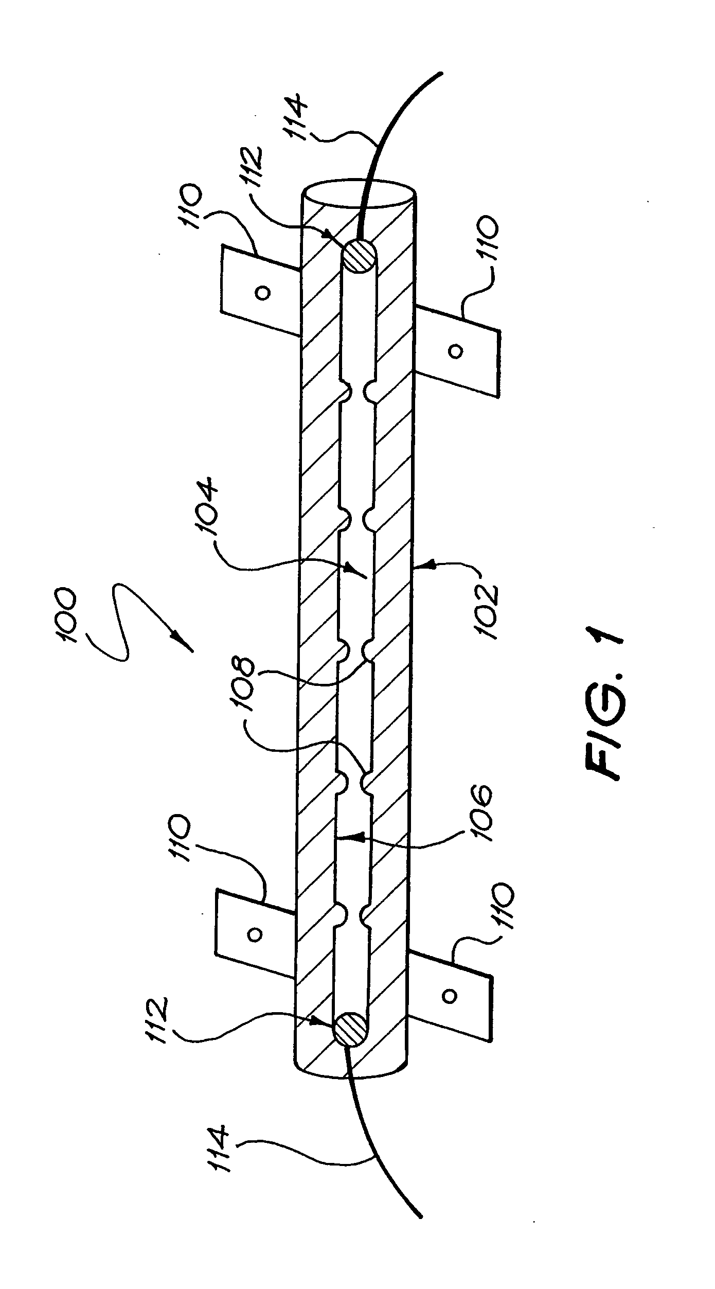
[0013] In this aspect, the impedance change may be enhanced by incorporating surface features on an inner wall of the tube that increase the influence of the change in the impedance of the conductive medium as a result of its being distorted.
[0019] When used on the bladder and the volume of the bladder is low, the conductors of the strips may be aligned and have a low resistive output. As the volume of the bladder increases the strips may follow the curvature of the wall of the bladder. As a result, the conductors of the strips may move out of alignment, increasing the resistive output to provide an indication of increase in bladder volume.
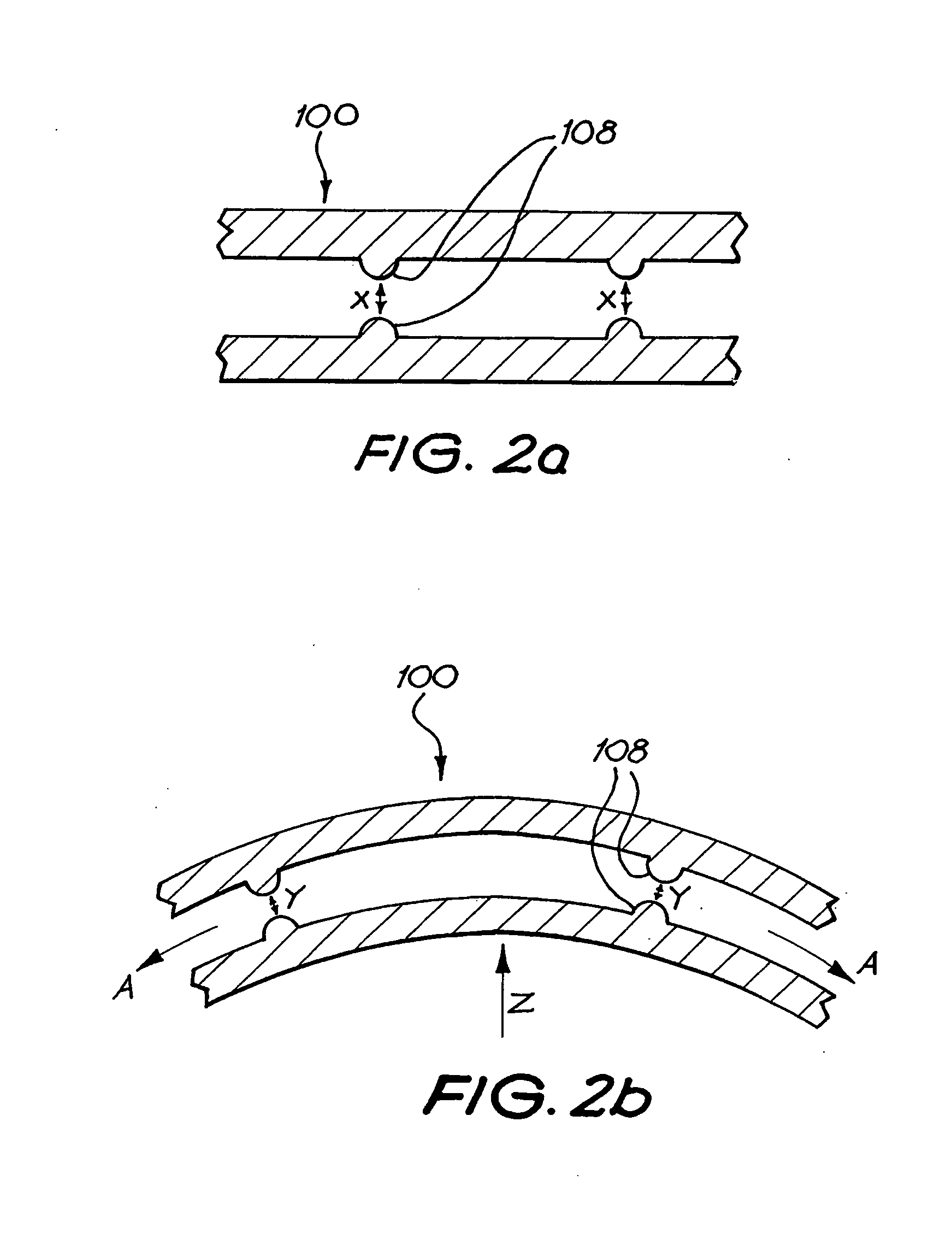
[0034] In this aspect, the housing is preferably stretched on an increase in volume of the organ thereby reducing the cross-sectional area of the housing and so increasing the impedance of the conductive material within the housing.
[0035] In one embodiment of this aspect, the housing can comprise a series of chambers in fluid communication with each other for receiving the conductive material, each chamber being defined at at least one end by diametrically opposed raised formations in the housing and wherein, on stretching of the housing, the opposed raised formations move relatively closer to each other thereby further increasing the impedance of the conductive material within the housing.

Problems solved by technology

Urinary and faecal incontinence are major health problems, particularly with an ageing population, for which there is no well-accepted medical treatment.
Such conditions can affect men and women of all ages and is a particularly prevalent problem for individuals suffering from spinal cord injury, such as tetraplegics, who may be unable to exercise volitional control over the detrusor muscle of his or her bladder and other functions such as bowel evacuation.

Method used


Image

  • Implantable bladder sensor
  • Implantable bladder sensor
  • Implantable bladder sensor

Examples


first embodiment

[0052] Referring initially to FIG. 1 of the drawings, an implantable bladder sensor, in accordance with the invention, for monitoring the condition of a person's bladder is illustrated and is designated generally by the reference numeral 100. In particular, the sensor 100 is used for monitoring the volume of fluid present in a person's bladder by monitoring the change in size and / or shape of the bladder. While the person is normally a human, the technique can apply equally to other animals.

[0053] The sensor 100 includes a carrier 102 which carries an impedance-varying means 104. The carrier 102 is a tube having closed ends. The tube 102 contains the impedance-varying means 104 which is in the form of a conductive fluid, such as saline solution.

[0054] An inner wall 106 of the tube 102 carries an impedance enhancing arrangement in the form of a series of diametrically opposed raised formations 108, thereby forming a series of chambers for receiving the impedance-varying means 104. Th...

second embodiment

[0061] Referring to FIG. 4 of the drawings, an implantable bladder sensor, in accordance with the invention, for monitoring the condition of a person's bladder is illustrated and is designated generally by the reference numeral 10. Once again, the sensor 10 is used in monitoring the volume of a person's bladder 12.

[0062] The sensor 10 includes a carrier 14 with an impedance-varying means 16 carried by the carrier 14.

[0063] In the embodiment of the invention shown in FIG. 4 of the drawings, the carrier 14 is a length of conductive silicone. The carrier 14 is attached to a wall 18 of the bladder 12 by, for example, sutures 20.

[0064] The impedance-varying means 16 is in the form of a probe 22 having a foot portion 24 which bears against an outer surface 26 of the wall 18 of the bladder 12.

[0065] When the bladder 12 has a low volume, the wall 18 of the bladder 12 is in a relaxed state and, as a result, the carrier 14 is similarly relaxed due to very little pressure, if any at all, be...

third embodiment

[0067] Referring to FIGS. 5 to 7 of the drawings, an implantable bladder sensor, in accordance with the invention, for monitoring the condition of a person's bladder is illustrated and is designated generally by the reference numeral 30.

[0068] The sensor 30 includes a carrier in the form of a sealed bag 32. The sealed bag 32 contains a non-conductive material in the form of a non-conductive solution 34. An impedance-varying means 36 is contained within the bag 32 and has leads 38 projecting through sealed ends of the bag 32. The ends are sealed in a manner to inhibit escape of the solution 34 from the interior of the bag 32.

[0069] The impedance-varying means 36 comprises a strip 40 of a non-conductive material. A side of the strip 40 which, in use, constitutes an operatively outer side (ie. that side of the strip 40 which is furthest away from the wall of the bladder) carries a layer of a conductive material 42.

[0070] As illustrated more clearly in FIGS. 6 and 7 of the drawings, t...


PUM


Abstract

An implantable sensor for monitoring the condition of an organ, such as the bladder, of a recipients' body. The sensor (100) comprises a carrier (102), such as a tubular housing that is attachable to the outer surface of the organ. An impedance-varying means (104), such as a saline solution, is carried by the carrier (102). The impedance-varying means (104) within the carrier varies as the condition of the organ changes to cause in output state of the sensor (100). The sensor (1000) can be used for the purposes of monitoring the filling of the bladder, making bladder volume information to the recipient or another person, and causing an alarm signal to be generated when a preset bladder volume is reached.

Description

FIELD OF THE INVENTION [0001] This invention relates to sensing a parameter of an organ of a person's body. More particularly, the invention relates to a device for sensing a parameter of a visceral organ of a person's body. BACKGROUND TO THE INVENTION [0002] Urinary and faecal incontinence are major health problems, particularly with an ageing population, for which there is no well-accepted medical treatment. Such conditions can affect men and women of all ages and is a particularly prevalent problem for individuals suffering from spinal cord injury, such as tetraplegics, who may be unable to exercise volitional control over the detrusor muscle of his or her bladder and other functions such as bowel evacuation. [0003] With the advent of Functional Electrical Stimulation (FES) Systems, such as that developed by the Applicant and described in International Patent Application No. PCT / AU03 / 00044, the contents of which are incorporated herein by reference, it is possible to control blad...

Claims


Application Information

Patent Timeline
IPC IPC(8): A61B5/05A61B5/11A61B5/20
CPCA61B5/204A61B5/6883
Inventor MILIJASEVIC, ZORANBARRISKILL, ANDREWBRUINSMA, IANNIEC, TOM
Owner NEOPRAXIS
Learn More