
Thermal switch with self-test feature

Active Publication Date: 2006-09-21
HONEYWELL INT INC
View PDF18 Cites 16 Cited by
  • Summary
  • Abstract
  • Description
  • Claims
  • Application Information

AI Technical Summary

Benefits of technology

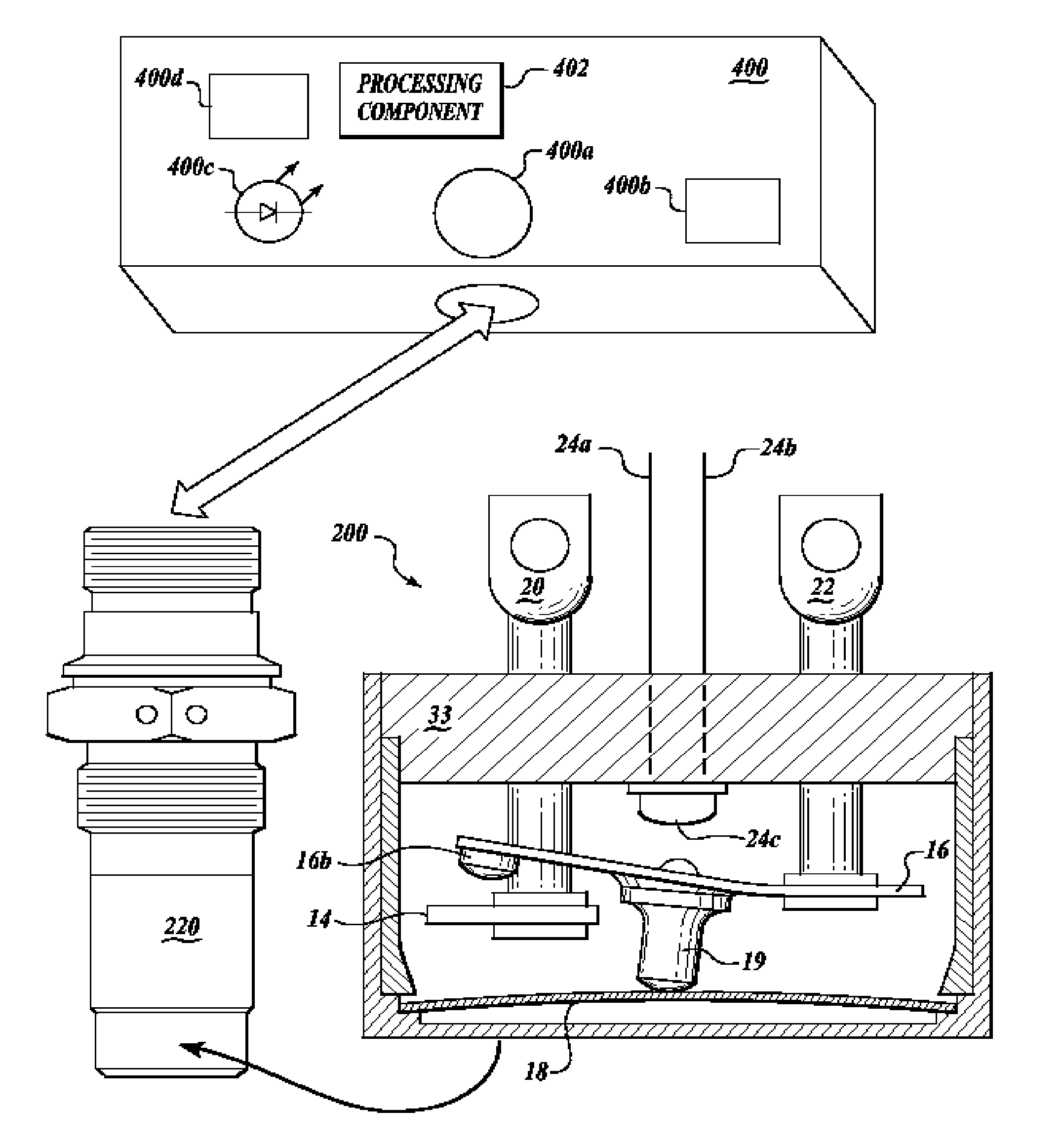
[0005] Embodiments provide a thermal switch test system that provides a ready indication that the thermal switch has experienced temperatures that triggered operation of the switch. Particular embodiments include a thermal switch with a heating element and a test box that is able to be coupled to the thermal switch at the installed position of the thermal switch so that temperature responsive actuator testing of the thermal switch may be conducted in situ, i.e., at the installed position of the thermal switch. The in situ testing of the thermal switch permits the advantageous testing without incurring the cost and inconvenience of thermal switch removal.

Problems solved by technology

Current snap-action thermal switches used in parallel operation, multiple thermal switch overheat detection systems suffer from various drawbacks.
The integrity of the wire harness between the cockpit and the wing tip cannot be assured because the circuit is always open under normal operating conditions.
Furthermore, if an overheat condition does occur, current snap-action thermal switches are not equipped to provide information describing the exact location of the overheat.
In both instances, flight safety is compromised, and later correction of the problem that caused the overheat condition is made more difficult because of the inability to pinpoint the overheat fault.
One application for thermal switches that clearly illustrates the disadvantages of prior art devices is duct leak overheat detection systems.
Thermal switches located along this duct, indicate overheating, which could otherwise lead to structure failure and other system failures.
Upon landing, the airplane maintenance personnel have no way of knowing which particular switch has been activated, because there exist multiple thermal switches linked to a particular cockpit light.
This dearth of information requires the crew to physically access and inspect the entire system along the appropriate wing semispan.
Even in applications where only one temperature probe indicated an alarm temperature in-flight, extensive and expensive troubleshooting is sometimes necessary.

Method used


Image

  • Thermal switch with self-test feature
  • Thermal switch with self-test feature
  • Thermal switch with self-test feature

Examples


Embodiment Construction

[0005] Embodiments provide a thermal switch test system that provides a ready indication that the thermal switch has experienced temperatures that triggered operation of the switch. Particular embodiments include a thermal switch with a heating element and a test box that is able to be coupled to the thermal switch at the installed position of the thermal switch so that temperature responsive actuator testing of the thermal switch may be conducted in situ, i.e., at the installed position of the thermal switch. The in situ testing of the thermal switch permits the advantageous testing without incurring the cost and inconvenience of thermal switch removal.

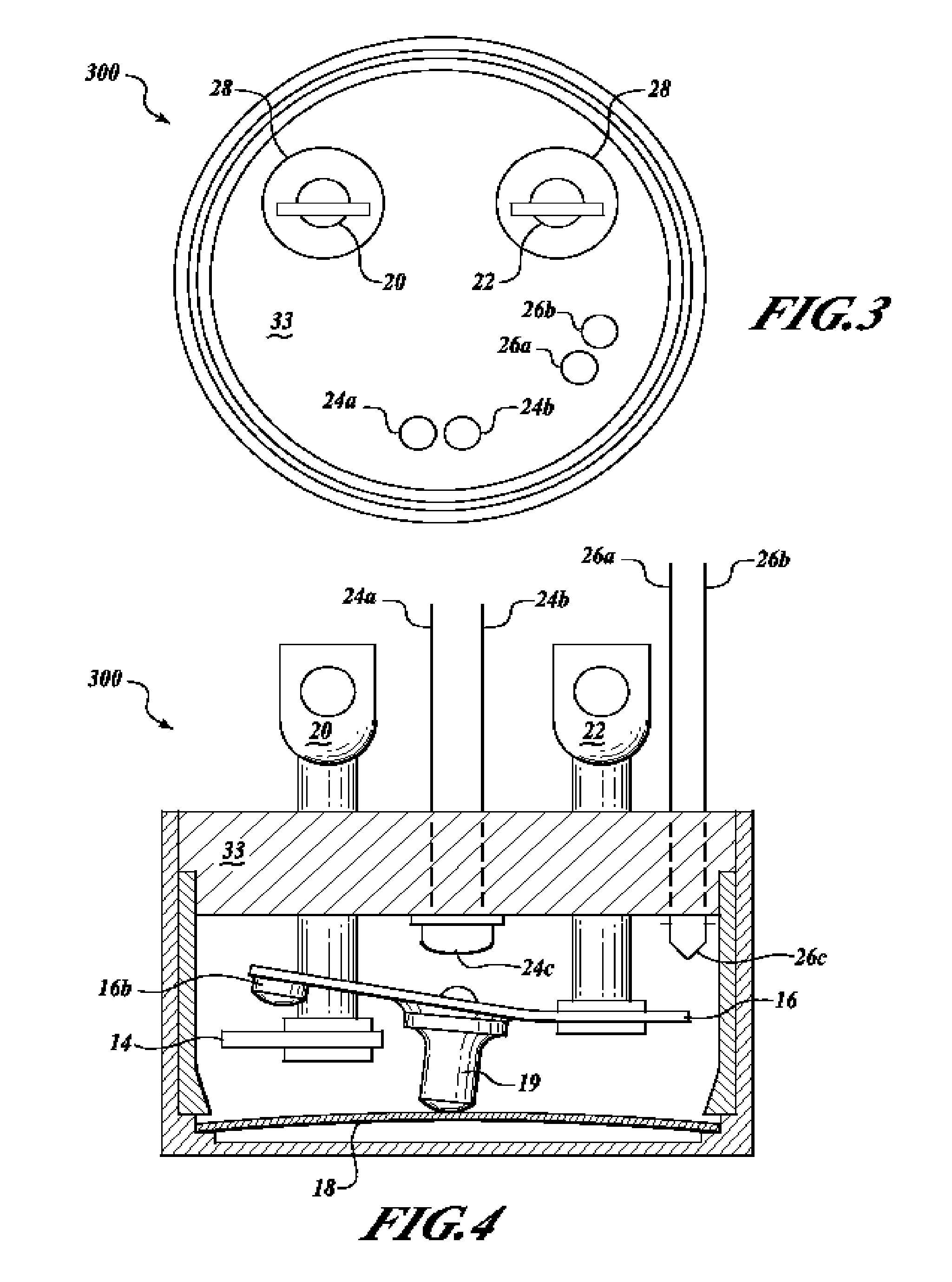
[0006] A particular embodiment includes a thermal switch having two pairs of four contacts in communication with a test box having an electrical power source, a temperature display, an event indicator, and a data recorder. The event indicator and temperature display communicates with the data recorder.

BRIEF DESCRIPTION OF THE DRAWIN...


PUM


Abstract

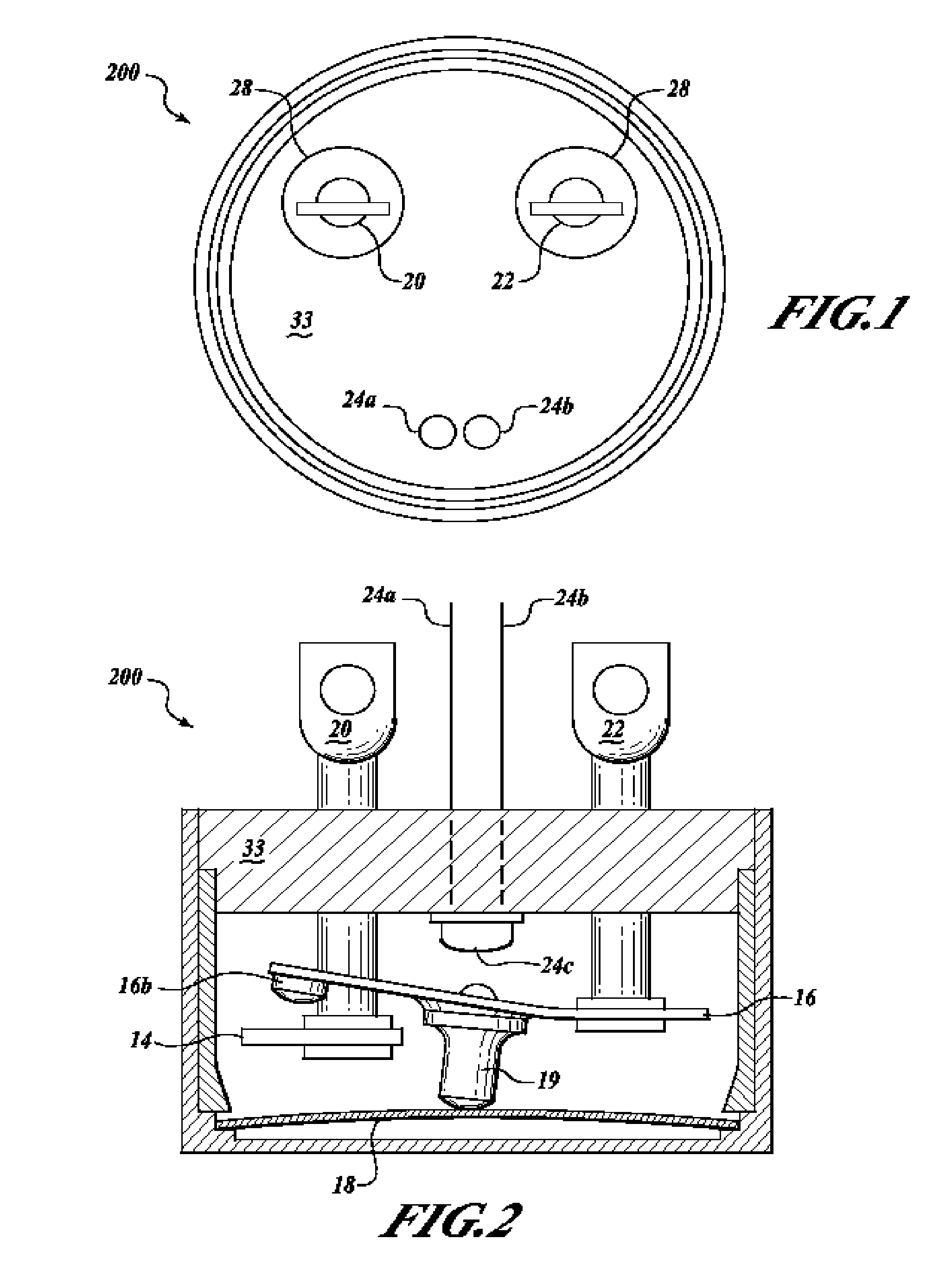
A normally open thermal switch (200) having a bimetallic disk (18) is configured for operational testing in its installed position when exposed to a changing temperature by a test box (400) having a power source (400a). The in-place testing advantageously confirms triggering action of the switch by an event indicator (400c) at the operational temperatures designed into the switch (200). The temperature of the triggering action is presented on a temperature display (400b) and recorded by a data recorder (400d) of the test box (400). The switch (200) incorporates a heating element (24c) to heat changing the bimetallic disk (18) to snap activate at the operative temperatures. The thermal switch (200) is coupled with the test box (400) to confirm its operation without having to remove the switch from its installed location.

Description

BACKGROUND OF THE INVENTION [0001] Thermal switches are used in a variety of applications where it is desirable to activate and / or deactivate equipment as a function of sensed temperature. Such applications may include: rocket motors and thrusters, battery charge rate control, temperature control for fuel systems, environmental controls, overheat protection as well as many others. In several thermal switch applications, it is desirable to know when the switch has been activated and at what temperature. For example, it is desirable to know that the switch is functioning correctly when the switch is part of a safety system or is part of a control system used to protect equipment. Snap-action thermal switches are utilized in a number of applications, such as temperature control and overheat detection of mechanical devices such as motors and bearings. In some applications, multiple thermal switches are located at different positions around the equipment. For example, in some aircraft wi...

Claims


Application Information

Patent Timeline
IPC IPC(8): H01H37/52H01H37/04
CPCH01H37/54H01H2300/052
Inventor DAVIS, GEORGE D.SCOTT, BYRON G.
Owner HONEYWELL INT INC
Learn More