
Improved shotgun barrel construction

a barrel and shotgun technology, applied in the field of improved shotgun barrel construction, can solve the problems of affecting the quality of finished products, and requiring considerable handwork, so as to reduce the recoil of felt, reduce the cost of production, and reduce the effect of manufacturing cos

Inactive Publication Date: 2006-09-21
LAZOR ERNEST R
View PDF24 Cites 10 Cited by
  • Summary
  • Abstract
  • Description
  • Claims
  • Application Information

AI Technical Summary

Benefits of technology

[0010] This invention simplifies and improves multiple barrel construction by introducing a muzzle block with extended chopper block as a shotgun barrel construction method. This construction method breaks the barrel assembly into four (4) types of components: 1) a muzzle block, 2) multiple barrel tubes, 3) an extended chopper block, and 4) ribs. The main principle behind this invention is to break the barrel assembly down into smaller components that are easier to manufacture to close tolerances, with emphasis on straightness and concentricity of the bore that positively influences overall shooting accuracy in a shotgun, and each component can be made from different materials that provide improved overall performance for that specific area of the barrel assembly.
[0011] The muzzle block allows for precise barrel alignment and regulation of all barrels since it is a single smaller part that can be more readily manufactured to close tolerances. This part can be made from a higher performance material which stands up better to the higher shock loads around the choke forcing cone area of the shotgun muzzle. Also this part can be heat treated and / or coated with performance materials to withstand the use of steel shot while allowing the barrel tubes to be treated differently for higher ductility.
[0012] The muzzle block comprises the area of the muzzle to through the choke forcing cone into a length of straight bore. This enables the containment of the choke area where the bore is choked down or constricted to the choke bore that produces the desired pattern at the target point. The muzzle block allows a choke tube to be screwed into the muzzle end to facilitate the use of different chokes for each barrel depending on the shooters needs or preferences. The muzzle block is threaded on the barrel tube end to accept the barrel tubes and provide a shock proof joint through the use of the threads and thread sealants, adhesives, or other medium.

Problems solved by technology

This process is tedious and requires considerable handwork to remove chemical fluxes and excess solder or braze.
Excessive heat from the process can also distort the barrels and impact the quality of the finished product.
Manufacturing a barrel set in this manner is time consuming and expensive while requiring a high degree of craftsmanship and luck to produce a quality barrel that will shoot consistently.

Method used


Image

  • Improved shotgun barrel construction
  • Improved shotgun barrel construction
  • Improved shotgun barrel construction

Examples


Embodiment Construction

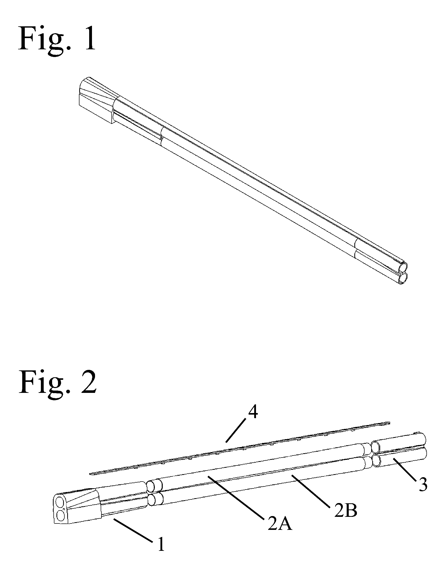
[0051] A complete barrel assembly is illustrated in the FIG. 1 perspective view of a multi-barreled shotgun barrel assembly.

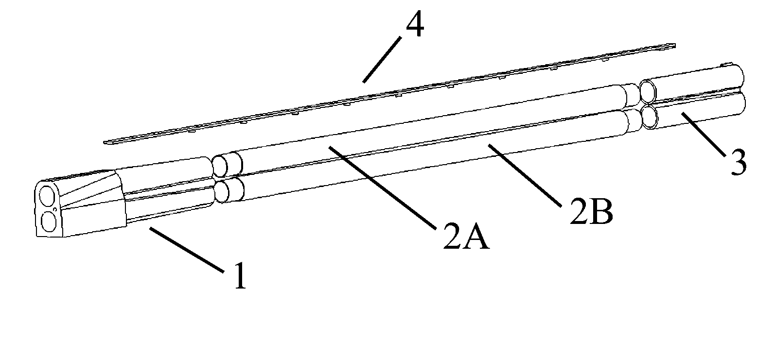
[0052] The barrel assembly is simplified into four main components in the FIG. 2 exploded view of the barrel assembly. These components are the Extended Chopper Block 1, the Upper Barrel Tube 2A, the Lower Barrel Tube 2B, the Muzzle Block 3, and the Top Rib Sighting Plane 4.

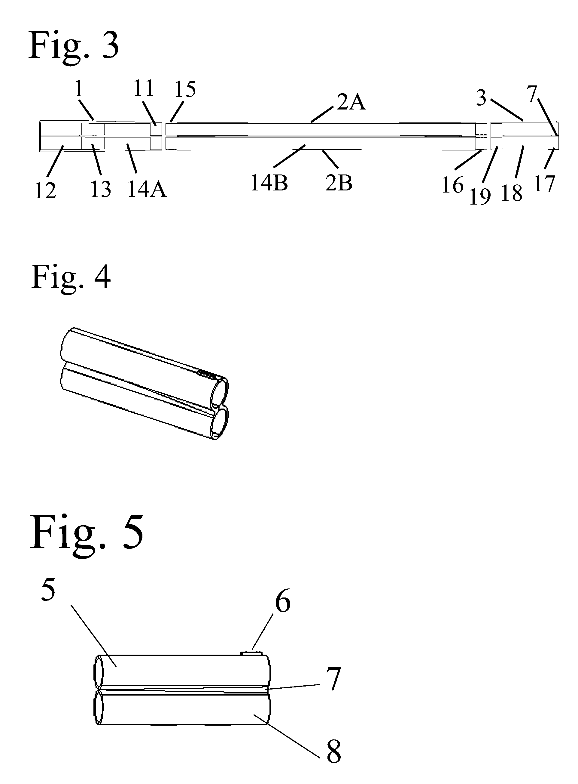
[0053]FIG. 3, exploded cross-sectional view of the barrel assembly, illustrates the internal features and characteristics of this type of barrel construction. The Extended Chopper Block 1 has a length sufficient to for a Shot Shell Chamber Area 12 providing for shot shells of all lengths along with an Extended or Long Forcing Cone Area 13 which transitions the shot column when the shotgun is fired from the chamber internal diameter to the Barrel Bore in the Extended Chopper Block 14A. This Extended Chopper Block construction contains all forces produced when firing the shot shells in the g...


PUM


Abstract

A multi-barreled shotgun barrel assembly construction, which breaks down barrel components into a Muzzle Block, Extended Chopper Block, and Barrel Tubes that join the two blocks enabling precise alignment to direct shot to a desired point of impact.

Description

BACKGROUND [0001] 1. Field of Invention [0002] This invention relates to firearms and more particularly to improvements in the construction and functionality of shotgun barrels. [0003] 2. Description of the Related Art [0004] Traditionally shotgun barrels construction has either been chopper lump or mono-block construction in multi-barreled shotguns. [0005] Chopper lump construction entails manufacturing barrel tubes in various ways and allowing extra material on the breech end. This extra material provided a way to join the barrels by forming this material into a dovetailed joint. Barrels are also shaved to create flat areas of contact to allow the barrels to fit closer together so lower overall heights and widths are achieved. This procedure reduces weight while lowering the overall height to provide a more naturally pointing firearm. [0006] The muzzle end of the barrel set, ribs for the top sighting plane and side covers are joined by soldering, brazing, or welding. All of these ...

Claims


Application Information

Patent Timeline
IPC IPC(8): F41A21/00
CPCF41A21/06F41A21/482
Inventor LAZOR, ERNEST R.
Owner LAZOR ERNEST R
Learn More