
Apparatus and method for displacing tissue obstructions

Inactive Publication Date: 2006-09-14
PYLES STEPHEN T
View PDF12 Cites 12 Cited by
  • Summary
  • Abstract
  • Description
  • Claims
  • Application Information

AI Technical Summary

Benefits of technology

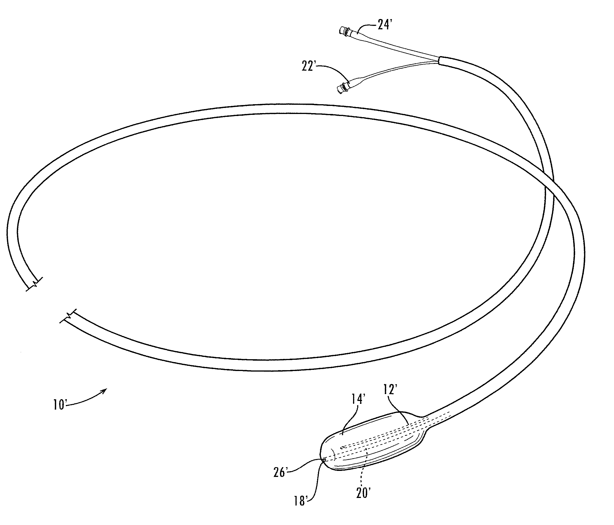
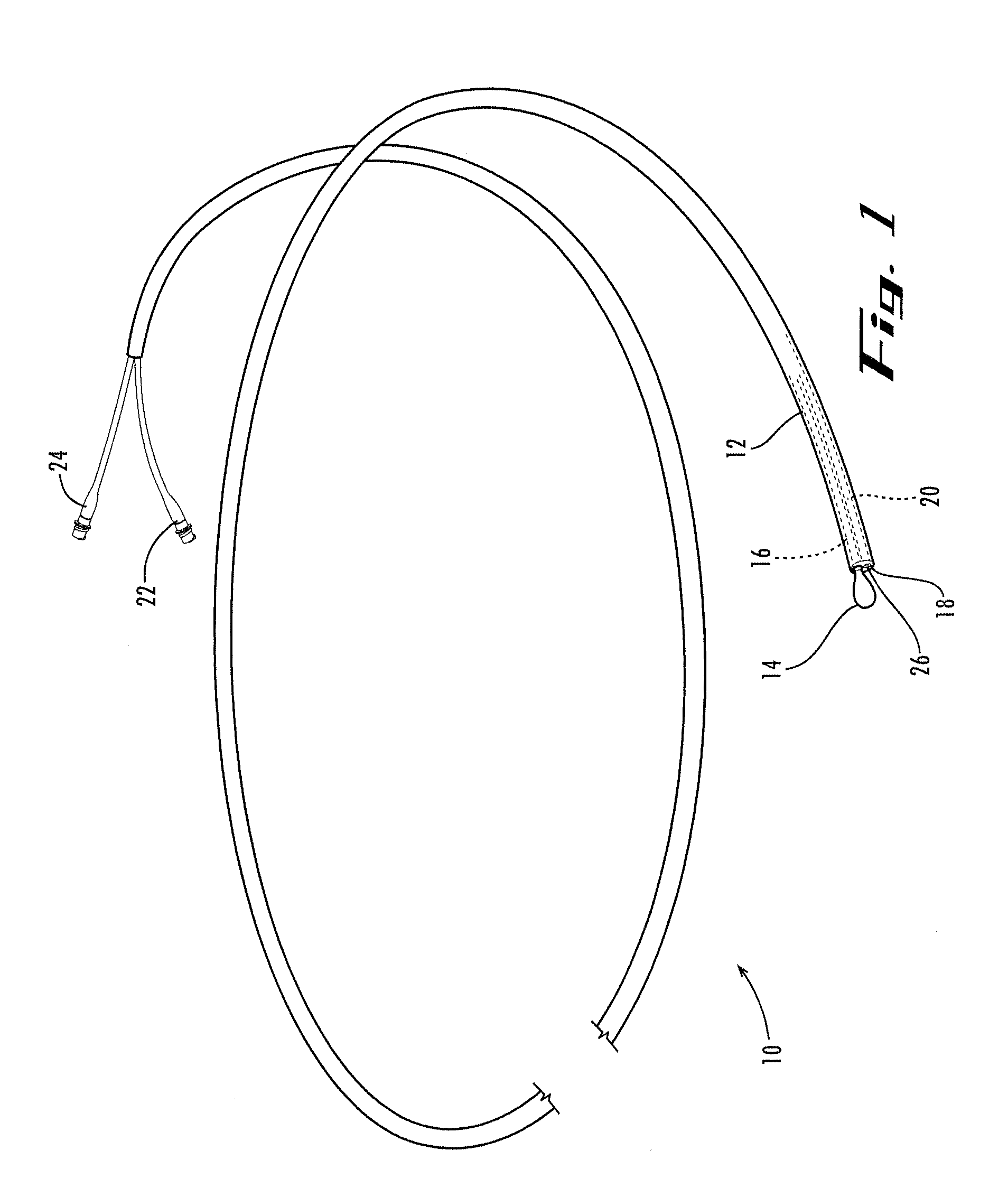
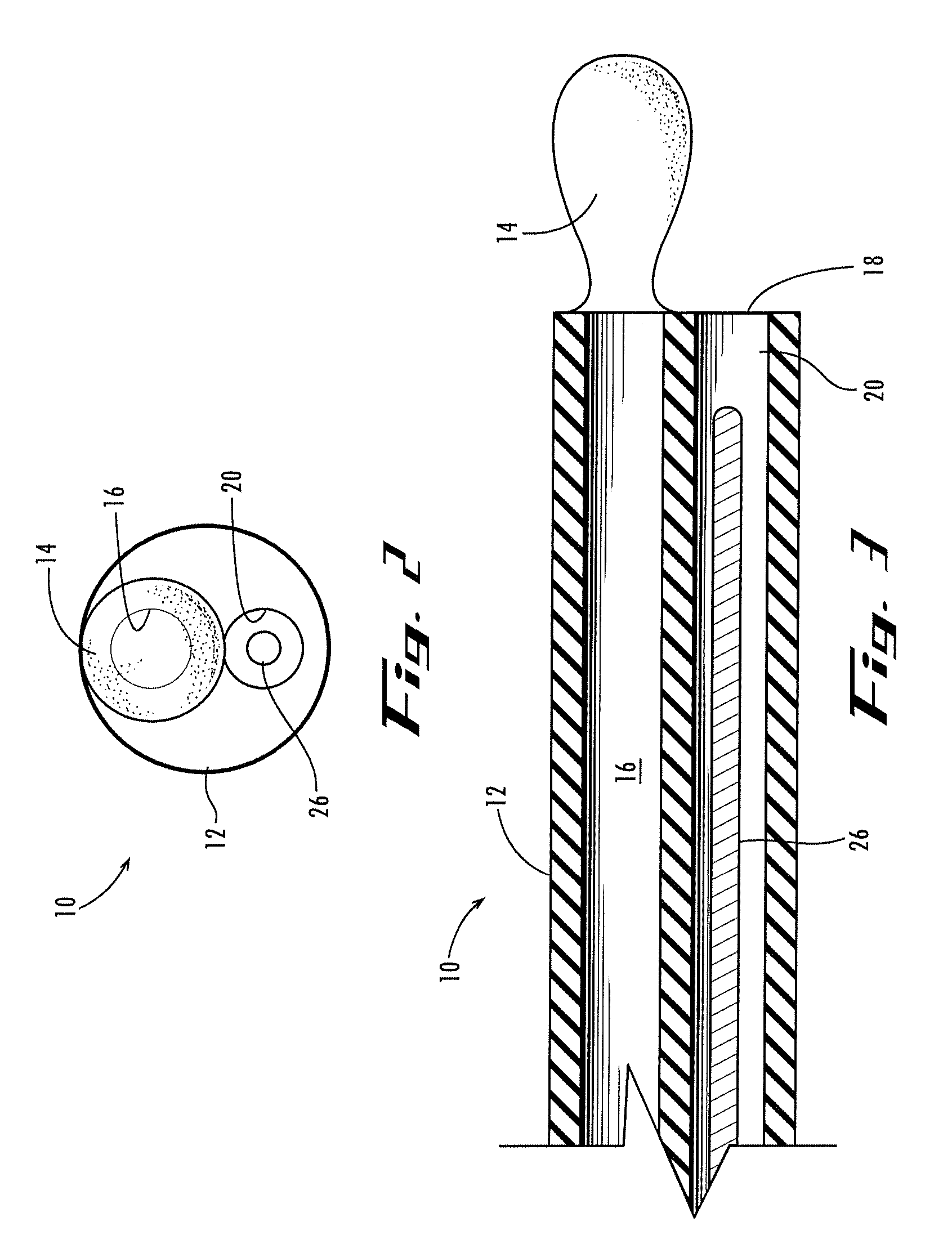
[0007] In example forms, the apparatus and method of the present invention provides a catheter for more effectively displacing tissue obstructions, such as lumbar epidural adhesions, fibrous connective tissue membranes, fat, and veins, when implanting spinal cord stimulator leads, such as percutaneous epidural leads or surgical leads, in the epidural space. The apparatus includes a catheter having a cuffed balloon for displacing obstructions and a fluid delivery port for injecting a saline solution to also displace the obstructions. Additionally, the catheter has a shape similar to that of the percutaneous epidural lead. The catheter's similarity in shape to that of a percutaneous epidural lead can create an adequate channel for the percutaneous epidural lead.

Problems solved by technology

As a result, the adhesions apply pressure on the nerves and nerve roots, which in turn causes the person to feel pain in his or her back or legs.
However, the use of fluids alone does not always provide sufficient results, as the adhesions may not break apart.
The presence of such adhesions, fat, veins, and connective tissue membranes interfere with the accurate placement of leads for spinal cord stimulation.
However, accurate placement of the leads can be difficult because the practitioner must navigate through or around such adhesions, fat, veins, and connective tissue membranes.

Method used


Image

  • Apparatus and method for displacing tissue obstructions
  • Apparatus and method for displacing tissue obstructions
  • Apparatus and method for displacing tissue obstructions

Examples


Embodiment Construction

[0021] The present invention may be understood more readily by reference to the following detailed description of the invention taken in connection with the accompanying drawing figures, which form a part of this disclosure. It is to be understood that this invention is not limited to the specific devices, methods, conditions or parameters described and / or shown herein, and that the terminology used herein is for the purpose of describing particular embodiments by way of example only and is not intended to be limiting of the claimed invention. Also, as used in the specification including the appended claims, the singular forms “a,”“an,” and “the” include the plural, and reference to a particular numerical value includes at least that particular value, unless the context clearly dictates otherwise. Ranges may be expressed herein as from “about” or “approximately” one particular value and / or to “about” or “approximately” another particular value. When such a range is expressed, anothe...


PUM


Abstract

A catheter for displacing tissue obstructions. The shaft of the catheter has first and second conduits extending therethrough. Preferably, the catheter has a distensible, cuffed balloon positioned around the distal end of its shaft, in fluid communication with the first conduit. The catheter preferably also has a fluid delivery port located at its distal end for discharging fluid from the second conduit. Preferably, the catheter also includes a stylet for guiding the catheter into and through the epidural space.

Description

CROSS-REFERENCE TO RELATED APPLICATIONS [0001] This application is a continuation-in-part of U.S. patent application Ser. No. 11 / 158,309, filed Jun. 21, 2005, which claims priority to both U.S. Provisional Patent Application Ser. No. 60 / 581,531, filed Jun. 21, 2004, and to U.S. Provisional Patent Application Ser. No. 60 / 640,648, filed Dec. 30, 2004. U.S. patent application Ser. No. 11 / 158,309 and Provisional Patent Application Ser. Nos. 60 / 581,531 and 60 / 640,648 are hereby incorporated herein by reference in their entireties for all purposes.TECHNICAL FIELD [0002] The present invention relates generally to the field of surgical methods and devices, and more particularly to an apparatus and method for displacing tissue obstructions. BACKGROUND OF THE INVENTION [0003] Lumbar epidural adhesions often occur as a result of a person undergoing back surgery. The adhesions, or scar tissue, tend to form around nerves and nerve roots. As a result, the adhesions apply pressure on the nerves an...

Claims


Application Information

Patent Timeline
IPC IPC(8): A61N1/05A61B17/20A61M31/00A61B19/00A61N1/00
CPCA61N1/0551A61M29/02A61M2025/0007
Inventor PYLES, STEPHEN T.
Owner PYLES STEPHEN T
Learn More