
Post operative knee brace with multiple adjustment features

a knee brace and multiple adjustment technology, applied in the field of orthopaedic knee braces, can solve the problems of complex adjustment mechanism and unusable us

Inactive Publication Date: 2006-09-14
TOWNSEND IND INC
View PDF17 Cites 44 Cited by
  • Summary
  • Abstract
  • Description
  • Claims
  • Application Information

AI Technical Summary

Benefits of technology

[0006] Thus, it is a goal of the present invention to provide a knee brace that will have adjustment mechanisms that are easy and economical to produce while being very user friendly. It is a further goal of the present invention to provide a knee brace that will be more comfortable to wear.
[0008] Contributing to attainment of the second goal, is a means for enabling the lateral-medial angulation of femoral strut to be adjusted relative to the joint mechanism and tibial strut.

Problems solved by technology

However, all of the known adjustment mechanisms have been complex and not very user friendly.
However, a need to be able to adjust the angle of the upper bar relative to the knee joint and lower bar in medial and lateral directions has not been found to exist up to this point.

Method used


Image

  • Post operative knee brace with multiple adjustment features
  • Post operative knee brace with multiple adjustment features
  • Post operative knee brace with multiple adjustment features

Examples


Embodiment Construction

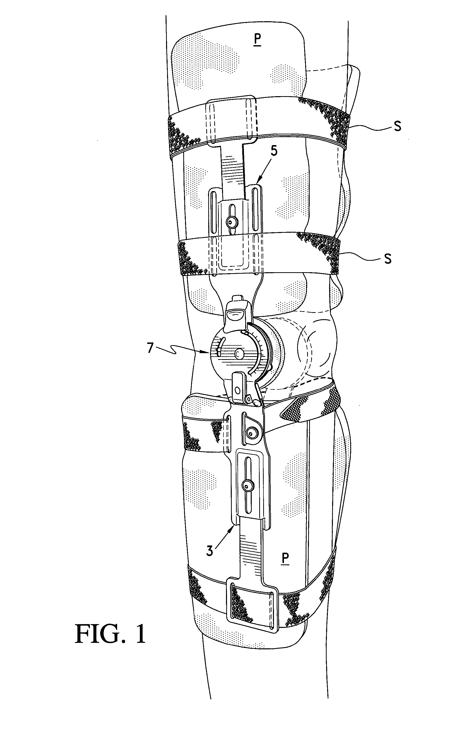
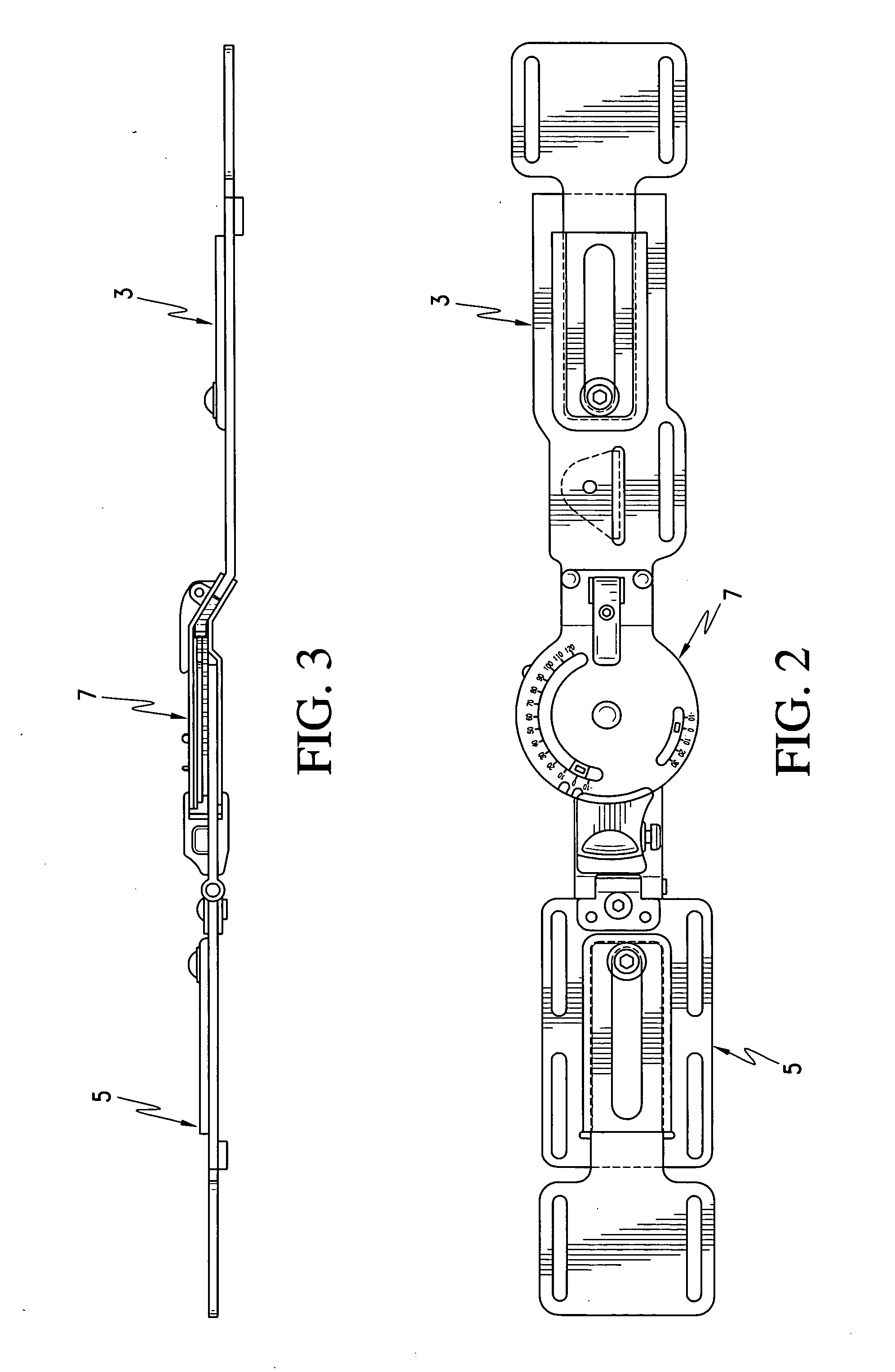
[0024]FIG. 1 shows a post-operative knee brace 1 in accordance with the present invention, and while only one side of the brace 1 is shown and described below, it is to be understood that identical structure is present on the opposite side of the brace 1 in mirror-image fashion. Thus, each side of the brace 1 has adjustable length tibial (lower) and femoral (upper) struts 3, 5, respectively. Each tibial strut 3 is connected to each femoral strut 5 by a joint mechanism 7. For attachment to the leg of the patient, a series of straps S are attached to the struts 3, 5 by being passed through slots in the struts and / or being attached to the struts via a fastener. Additional, for comfort purposes, pads P are provided on the inner sides of the struts 3, 5. To this extent, the brace 1 conforms with known knee braces.

[0025] As can be seen most clearly in FIGS. 4-8, the adjustable length struts 3, 5 are comprised of a joint connector part 3a, 5a and an extension part 3b, 5b. The extension pa...


PUM


Abstract

A knee brace having adjustment mechanisms that are easy and economical to produce while being very user friendly, and which is more comfortable to wear. The brace has a joint mechanism formed of a plurality of plates with notches, openings and range of motion surfaces, the relative positions of which are used as part of a flexion-extension stop arrangement and also as part of an adjustable locking arrangement by which the brace can be locked, temporarily released or indefinitely released. Furthermore the lateral-medial angulation of the femoral strut is able to be adjusted relative to the joint mechanism and tibial strut.

Description

BACKGROUND OF THE INVENTION [0001] 1. Field of the Invention [0002] The invention relates to orthopedic knee braces and in particular to post-operative knee braces as are commonly applied to the leg of a patient that is convalescing from knee surgery to enable the leg to be rehabilitated without reinjuring of the knee. Such knee braces routinely feature two rigid bars, hinges that can be adjusted to fix the brace so as to preclude flexing of the knee or to limit the extent to which the patient can extend and / or flex the leg. Typically, straps are provided for securing the brace to the leg and pads act to provide a comfortable interface between the bars and hinges and the patient's leg. [0003] 2. Description of Related Art [0004] Numerous examples of knee braces of the initially mentioned type and hinges for such knee braces can be found in the art. U.S. Pat. Nos. 4,463,751; 4,982,732; 5,000,169; 5,105,805; 5,409,449; 5,460,599; and 5,814,000 are representative of post-operative knee...

Claims


Application Information

Patent Timeline
Patent Type & Authority Applications(United States)
IPC IPC(8): A61F5/00
CPCA61F5/0125A61F2005/0134A61F2005/0167
Inventor TOWNSEND, JEFFREY H.KNECHT, STEVEN S.
Owner TOWNSEND IND INC
Learn More