
Method and arrangement for stressing a staggered anchorage

a staggered anchorage and tensioning technology, applied in mining structures, excavation, foundation engineering, etc., can solve the problems of varying tension states, high cost, and difficulty in adjusting and achieve the effect of improving the load behavior of the staggered anchorage and simplifying the tensioning operation

Inactive Publication Date: 2006-09-14
DYWIDAG SYST INT GMBH (DE)
View PDF10 Cites 19 Cited by
  • Summary
  • Abstract
  • Description
  • Claims
  • Application Information

AI Technical Summary

Benefits of technology

[0011] It is therefore an object of the present invention to provide a method and an arrangement for tensioning staggered anchorages that simplifies the tensioning operation and improves the load behavior of a staggered anchorage when overelongated.
[0014] The great benefit derived therefrom is such that when tensioned beyond the working load until the maximum allowable load of the staggered anchorage is reached, all tension members have the same bearing reserves, irrespective of their lengths. The maximum allowable load thereby corresponds to the state of tension of the staggered anchorage, whereby all tension members are impacted with the predetermined maximum load, preferably the test load Fp. Thus, a beneficial feature of a staggered anchorage of the present invention is great safety from failure.
[0017] The initial advantage of this method is that only one jack is needed for the tensioning operation. This can be a commercially available multistrand jack, whereby the user of a method of the present invention is merely faced with minor investment expenditures as compared to the use of monojacks. The tensioning of a staggered anchorage is limited to only one stroke and is thus quickly accomplished. Since only one jack is utilized, there is little expenditure for measuring and logging tasks. The benefit of the invention is a simple operation and quick execution of the tensioning procedure, which last but not least increases its economic efficiency.
[0018] After tensioning the tension members to the predetermined maximum load, the staggered anchorage is adjusted to the service load state. Again, a state is thereby generated, whereby the individual tension members are all less elongated at the identical value, as compared to the elongation under the predetermined maximal load. Thus, under the working load of the staggered anchorage, all tension members have identical elongation reserves before reaching the predetermined maximal load. If the staggered anchorage is overelongated in the service state, the anchorage force can therefore be increased without overtensioning the anchorage. The highest efficiency and thus maximum load capacity is achieved when the predetermined load is reached simultaneously in all tension members. Thus, a pretensioned staggered anchorage according to the present invention provides optimum safety from overelongation while allowing a simple and quick execution of the tensioning operation.

Problems solved by technology

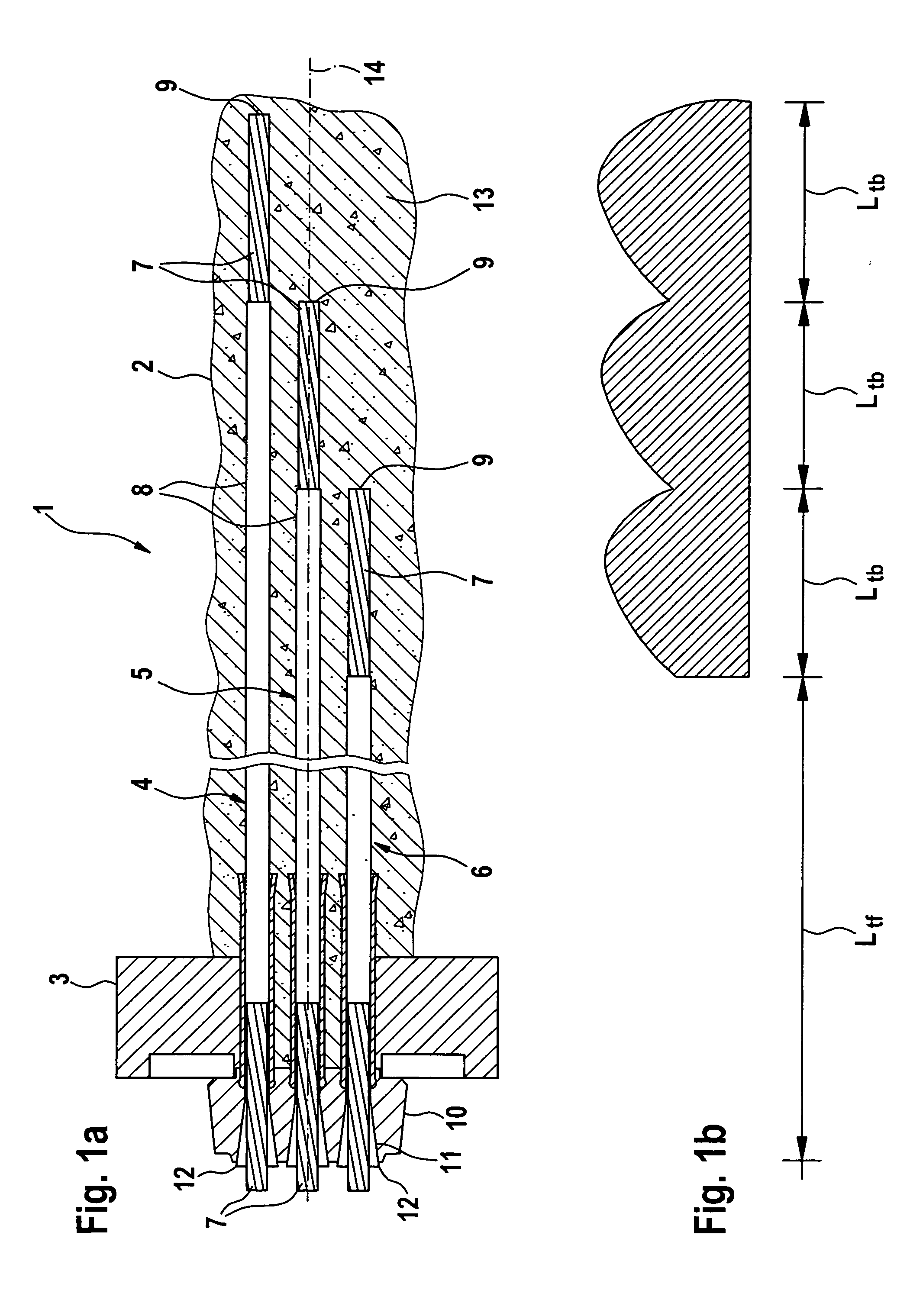
In contrast, the problem with tensioning staggered anchorage is that with uniform elongation of all tension members, varying states of tension would occur due to their different free steel lengths Ltf.
The necessity to have on hand and to operate multiple monojacks, has proven to be extremely costly, both technically and economically.
In addition, using multiple monojacks entails considerable expenditures for the required measuring and logging labor.
Although, from a technical viewpoint, applying a uniform working load to the individual tension members helps achieve a high anchorage force, however, it has the disadvantage that in the event of unexpected elongation of the anchorage, for example, due to deformations below ground, the elongation reserves of the individual tension members are different.
With tension members of shorter free steel lengths, the reserves will be used up after a short overelongation, thus running the risk that these tension members fail.

Method used


Image

  • Method and arrangement for stressing a staggered anchorage
  • Method and arrangement for stressing a staggered anchorage
  • Method and arrangement for stressing a staggered anchorage

Examples


Embodiment Construction

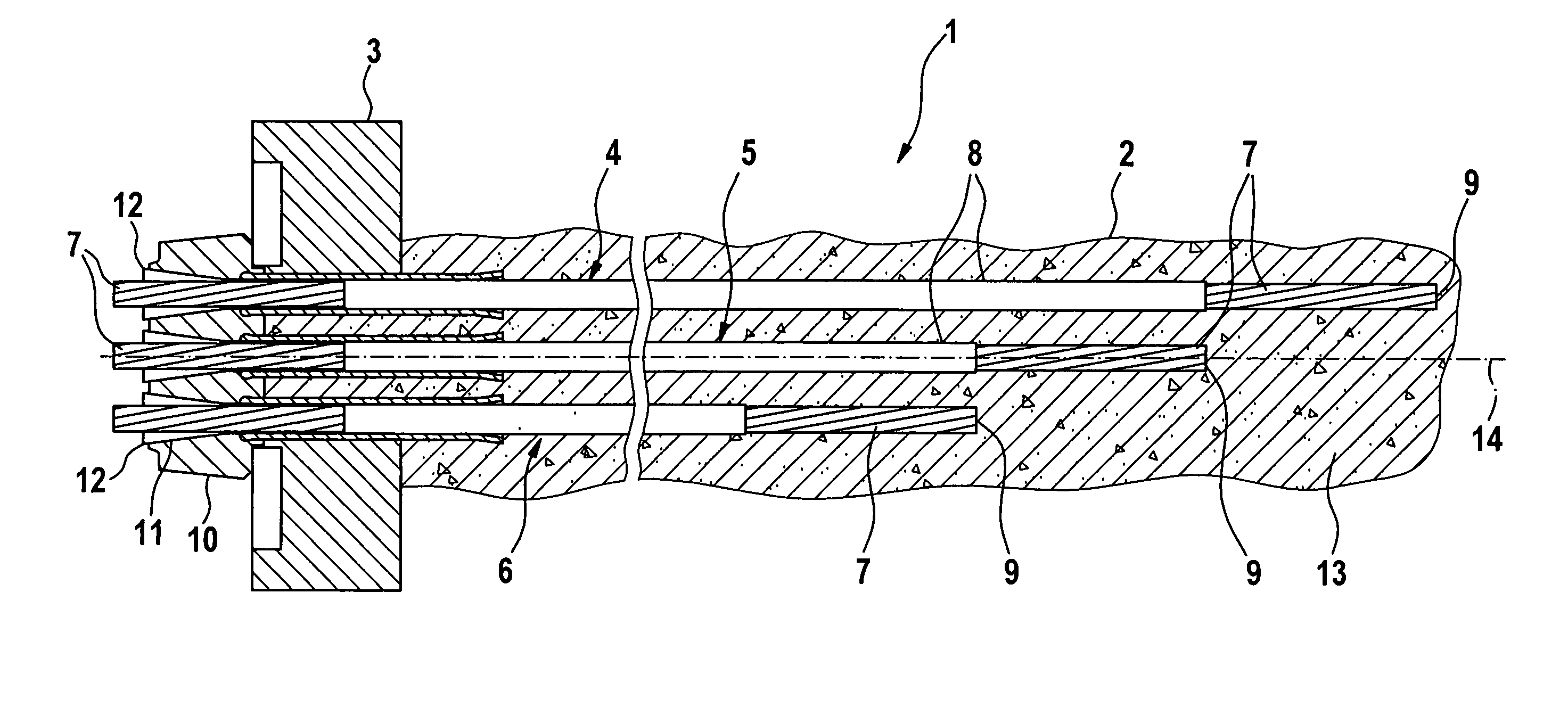
[0031]FIG. 1 shows a ground anchorage as a staggered anchorage 1 in a service state. The staggered anchorage 1 is guided into a bore hole 2, the top opening of which is enclosed by a base plate 3. The base plate 3 has a central opening, through which the staggered anchorage 1 extends with its above-ground end. A longitudinal axis of the staggered anchorage 1 has the reference numeral 14.

[0032] The staggered anchorage 1 includes a plurality of axis-parallel tension members 4, 5, and 6. Each tension member 4, 5, and 6 has a steel wire strand 7, which along most of its length is provided with a sheathing 8. In contrast, the end 9 of the steel wire strand 7 assigned to the bottom of the bore hole remains bare. Due to the different lengths of the tension members 4, 5, and 6, an arrangement of the ends 9 of the steel wire strands 7 in the bore hole 2 is formed that is staggered in the longitudinal direction 14 of the staggered anchorage 1.

[0033] The opposite, above-ground ends of the te...


PUM


Abstract

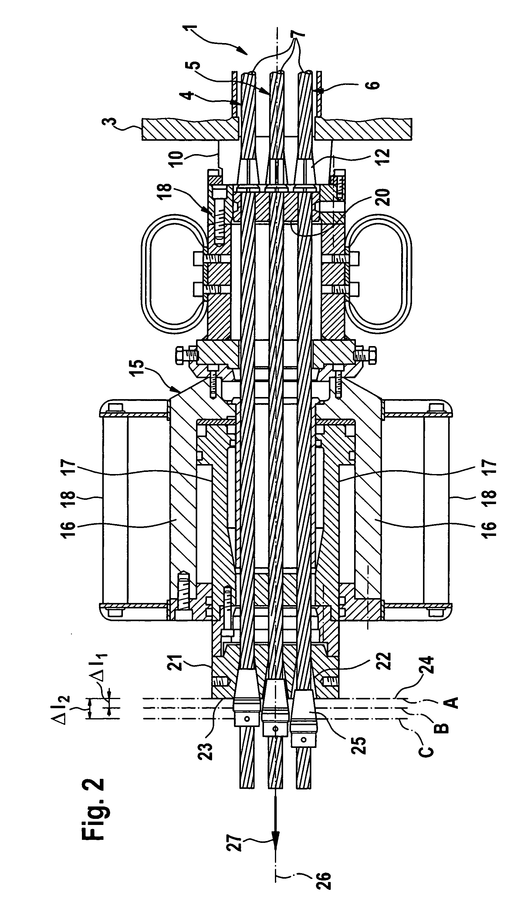
A method and apparatus for tensioning a staggered anchorage comprised of a plurality of tension members, which are anchored in a bore hole at various depths, thus having different free steel lengths. For each staggered anchorage, each tension member is tensioned up to a predetermined maximal load and is then subsequently adjusted to the working load. To achieve a consistent elongation reserve of the individual tension member and thus to increase the security of a staggered anchorage, the staggered anchorage is adjusted to the working load, all tension members are adjusted to a reduced elongation (ΔIw) by a uniform elongation difference (ΔImax−ΔIw) relative to the respective elongation (ΔImax) of the predetermined maximal load. An arrangement for performing the method has a single tensioning plane, which is force interconnected with defined locking elements that are arranged on tension members in clamping planes.

Description

[0001] This nonprovisional application claims priority under 35 U.S.C. § 119(a) on German Patent Application No. DE 2005 010 957.8-25, which was filed in Germany on Mar. 10, 2005, and which is herein incorporated by reference. BACKGROUND OF THE INVENTION [0002] 1. Field of the Invention [0003] The present invention relates to a method and an arrangement for tensioning a staggered anchorage. [0004] 2. Description of the Background Art [0005] Pressure-grouted anchorages are known, for example, as ground or rock anchorages. They are generally comprised of a plurality of axis-parallel tension members of steel rods, steel wires, or steel wire strands, which are guided into a bore hole. By grouting at the furthest end of the bore hole, a grouted body is formed, which bonds the tension members with the surrounding ground for transmitting a load to the underground. The longitudinal segment of a tension member, which facilitates load transfer, is referred to as an anchorage length Ltb. At th...

Claims


Application Information

Patent Timeline
Patent Type & Authority Applications(United States)
IPC IPC(8): E02D5/74E04B1/00
CPCE02D5/808
Inventor LANGWADT, OTMARSCHMIDT, FRANK
Owner DYWIDAG SYST INT GMBH (DE)
Learn More