
Low cost indoor test facility and method for mobile satellite antennas

a low-cost indoor and test facility technology, applied in the direction of antenna radiation diagrams, transmission monitoring, receiver monitoring, etc., can solve the problems of high cost and impracticality of such ranges in a mass production testing environmen

Inactive Publication Date: 2006-09-07
RAYSAT ANTENNA SYST L L C
View PDF8 Cites 13 Cited by
  • Summary
  • Abstract
  • Description
  • Claims
  • Application Information

AI Technical Summary

Benefits of technology

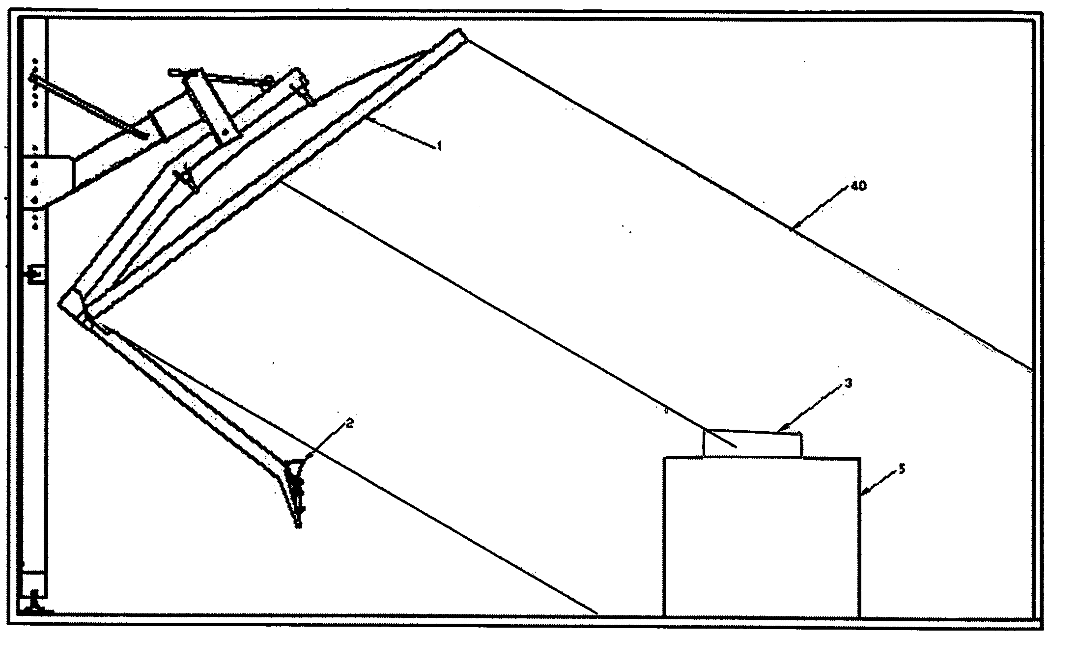
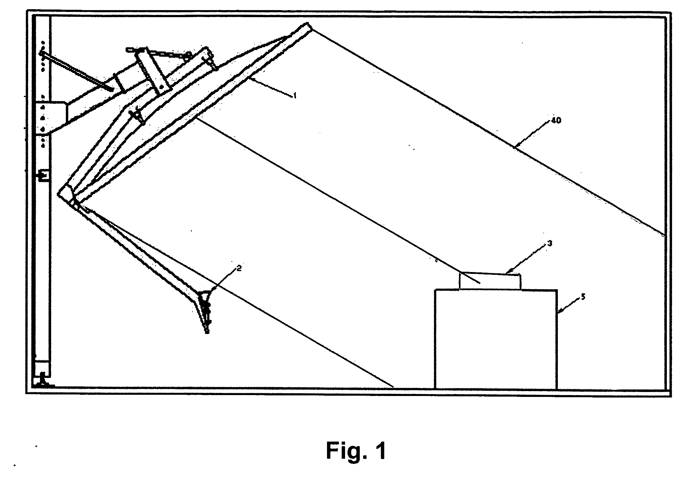
[0007] According to one exemplary embodiment of the invention, a simple off the shelf reflector antenna is used to generate a plane wave in the area where the antenna terminal under test is situated. The diameter of the reflector is chosen to be larger than the antenna under test in order to ensure relatively uniform amplitude and phase distribution of the electromagnetic field over the test area. A reflector with an off set geometry is preferable in order to minimize shadowing and to ensure better planarity of the wave in the near field plane wave region. An off-the-shelf reflector may be used with the present invention, since the objective is to conduct final system tests (for example acquisition and tracking antenna capabilities) or to determine antenna parameters required by a defined specific acceptance test procedure.

Problems solved by technology

Such compact range facilities typically require a very precise reflector surface for the accurate measurement of the antenna parameters, resulting in high cost.
Furthermore, highly skilled personal are typically needed to perform the tests, which are time consuming thereby making impractical such ranges for a mass production testing environment.

Method used


Image

  • Low cost indoor test facility and method for mobile satellite antennas
  • Low cost indoor test facility and method for mobile satellite antennas
  • Low cost indoor test facility and method for mobile satellite antennas

Examples


Embodiment Construction

[0017] The claims alone represent the metes and bounds of the invention. The discussed implementations, embodiments and advantages are merely exemplary and are not to be construed as limiting the present invention. The description of the present invention is intended to be illustrative, and is not intended to limit the scope of the claims. Many alternatives, modifications and variations will be apparent to those skilled in the art.

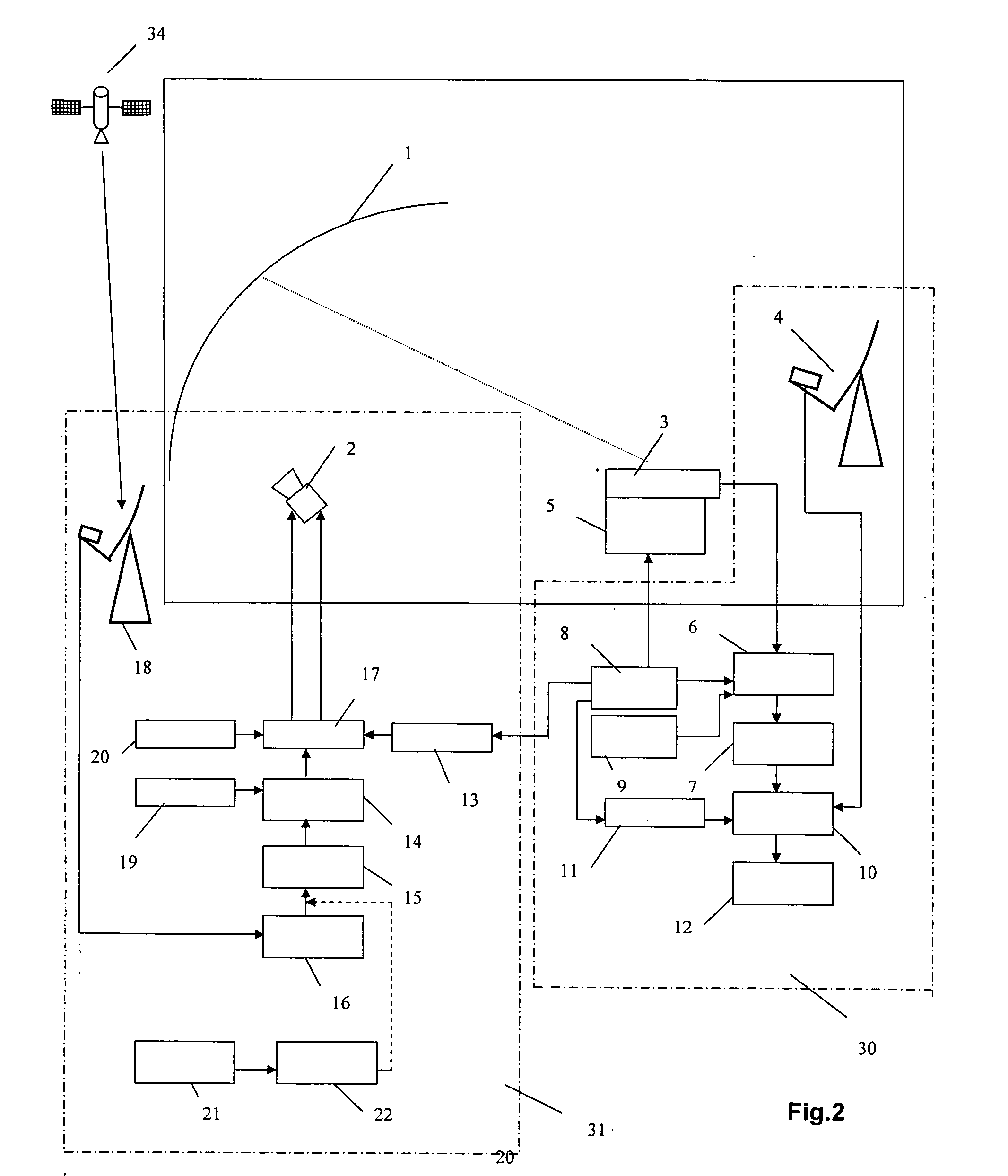
[0018] The present invention may be exemplified by several applications of the methods and system embodying low cost facilities for indoor testing of mobile antennas for broadband satellite (or terrestrial) communications using an antenna reflector test range with plane wave supplied by a standard off-the-shelf reflector antenna and an actual or simulated satellite (or other type) signal provided by either an auxiliary antenna or a DVB streamer.

[0019] One exemplary embodiment of the low cost antenna reflector test range configuration is illustrated in FI...


PUM


Abstract

A test system and method for indoor testing of a mobile antenna terminal having a first antenna with a first aperture of a first size and, preferably, operable in a receive-only mode and / or a transmit and receive mode. The system uses a second antenna having a dual port feed and a reflector, the second antenna having a second aperture of a second size, which is two or more times the first size, and being operative to form a plane wave. The first antenna is mounted to a test platform that is positioned within the second aperture and is operative for rotating and tilting movement of the antenna to simulate movement on a vehicle. The test system uses a source of RF test signals and communications test equipment coupled to at least the first antenna, as well as a processor for determining a performance of the mobile antenna terminal.

Description

FIELD OF INVENTION [0001] The present invention refers to a method and apparatus for indoor rapid and cost-effective tests of mobile tracking antennas for satellite (or terrestrial) communications. [0002] In particular, the invention concerns a low cost antenna test range based on a standard off-the-shelf reflector antenna, a mobile environment simulation device, and a source of an actual modulated satellite signal or a simulated satellite (or another type) signal to the test antenna. The tracking and recognition capabilities of a mobile antenna terminal may be tested in a compact indoor environment. The disclosed method and apparatus permits a rapid assessment and diagnosis, including final production tests, of receive only or two-way (receive and transmit) mobile antenna terminals for broadband satellite (or terrestrial) communications. The invention permits a simple test set-up requiring minimal training of personnel. BACKGROUND OF THE INVENTION [0003] Designs and techniques for ...

Claims


Application Information

Patent Timeline
Patent Type & Authority Applications(United States)
IPC IPC(8): H04B17/00
CPCH04B17/20G01R29/10
Inventor SPIRTUS, DANNY
Owner RAYSAT ANTENNA SYST L L C
Learn More