
Automated traffic control system

a technology of automatic traffic control and control system, applied in the direction of traffic signals, instruments, roads, etc., can solve the problems of control devices still require one operator, and inefficient movement of timing circuit traffi

Inactive Publication Date: 2006-09-07
HAMMETT JUANITA I
View PDF14 Cites 29 Cited by
  • Summary
  • Abstract
  • Description
  • Claims
  • Application Information

AI Technical Summary

Benefits of technology

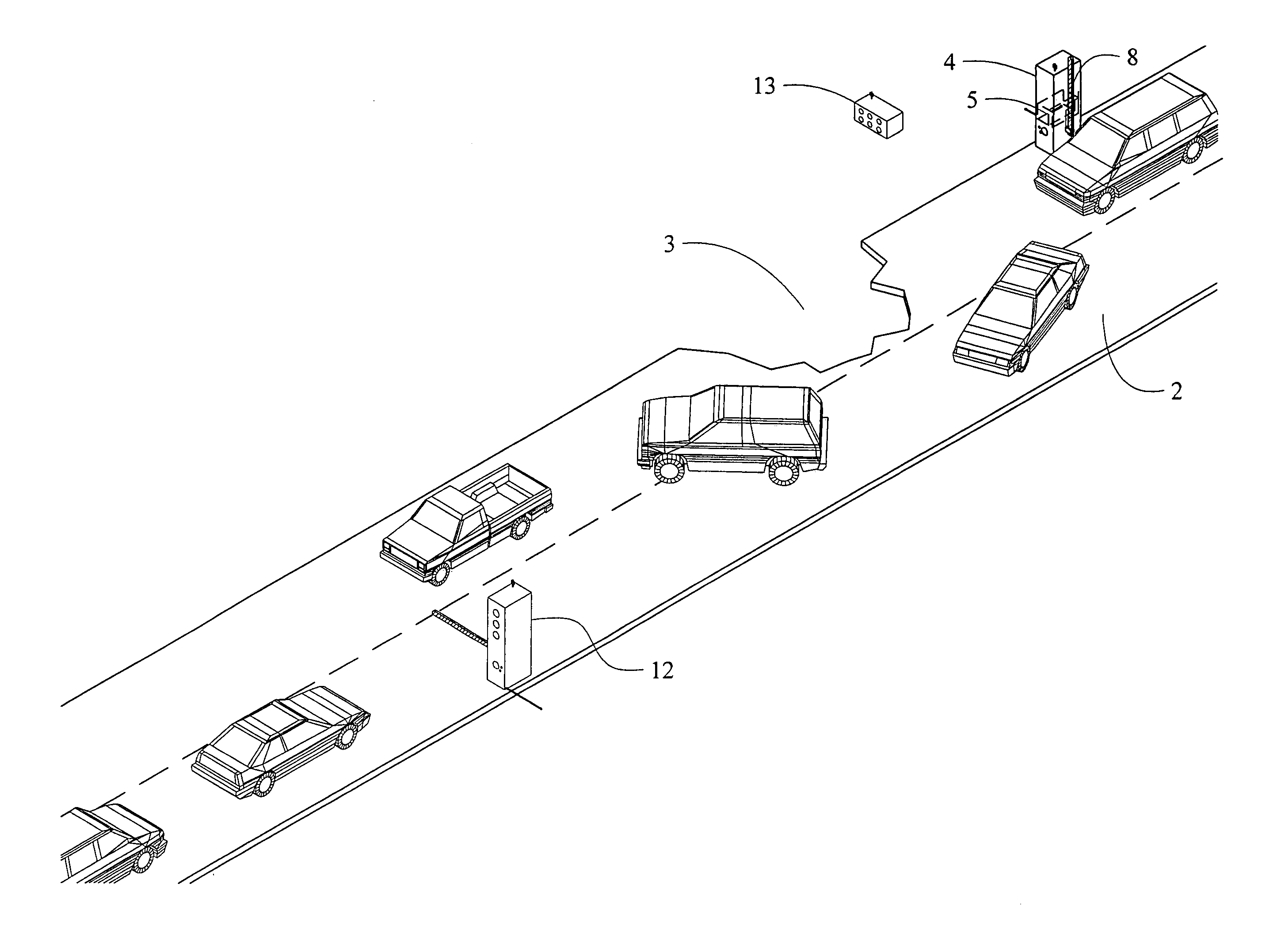
[0020] Generally, the present invention provides a system that emulates the actions and decisions of flagmen to control and to expedite traffic along a single lane past road construction or other obstacle. The present invention has two portable traffic signal light units with lift gates. One unit, designated the master unit, has a computer that controls the system as well as three video cameras and two way radio communication. The other unit, designated the slave unit, has three cameras and radio communication to the master unit. A hand held remote control is also provided for starting and stopping the system along with a manual override of the system if needed. The system has a coding feature maintained by the remote control so that only the remote control can start and stop the system. The coding feature deters theft and interference by other radio sources. The system also protects itself against vandalism and functions during periods of obscured vision such as inclement weather and darkness.
[0027] Another object is to provide an automated traffic control system that can be easily and efficiently manufactured and marketed to the consuming businesses and government entities.

Problems solved by technology

However, the remote control devices still require one operator and the timing circuits move traffic inefficiently.
Regarding traffic moving inefficiently, timers on signals at road construction have a set pattern for lights controlling traffic but the pattern does not adjust for variations in traffic volume.
Traffic may accumulate at either entrance or exit while the simple timer cycles, as if the traffic approaches each end of the construction evenly, causing unnecessary delay and potentially lengthy backups.
However, this patent lacks sensors to detect vehicles and lacks gate arms.
However, this patent has a two sided flat sign with lights, mechanical gears to turn the sign, and no red yellow green traffic lighting.

Method used


Image

  • Automated traffic control system
  • Automated traffic control system
  • Automated traffic control system

Examples


Embodiment Construction

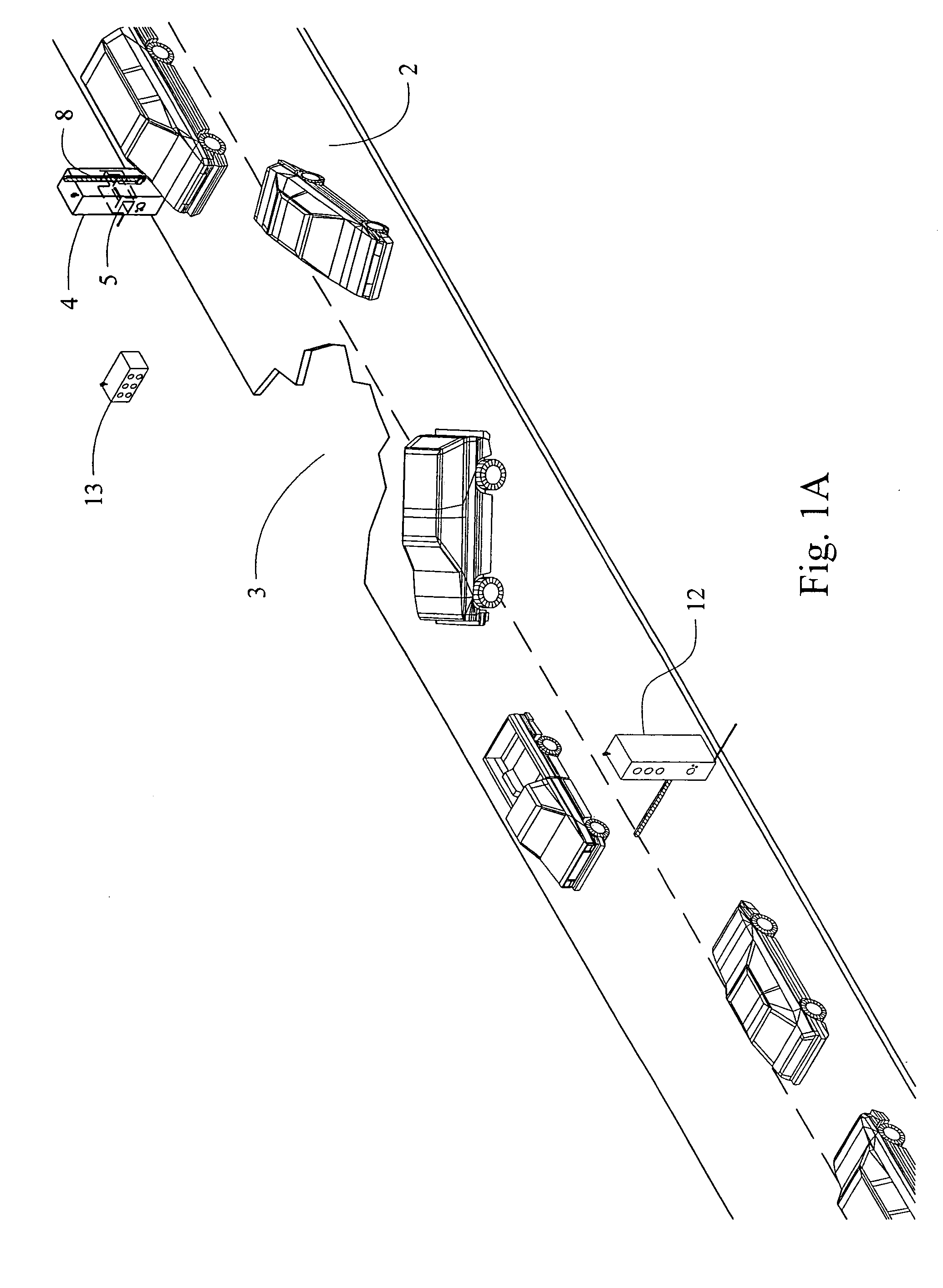
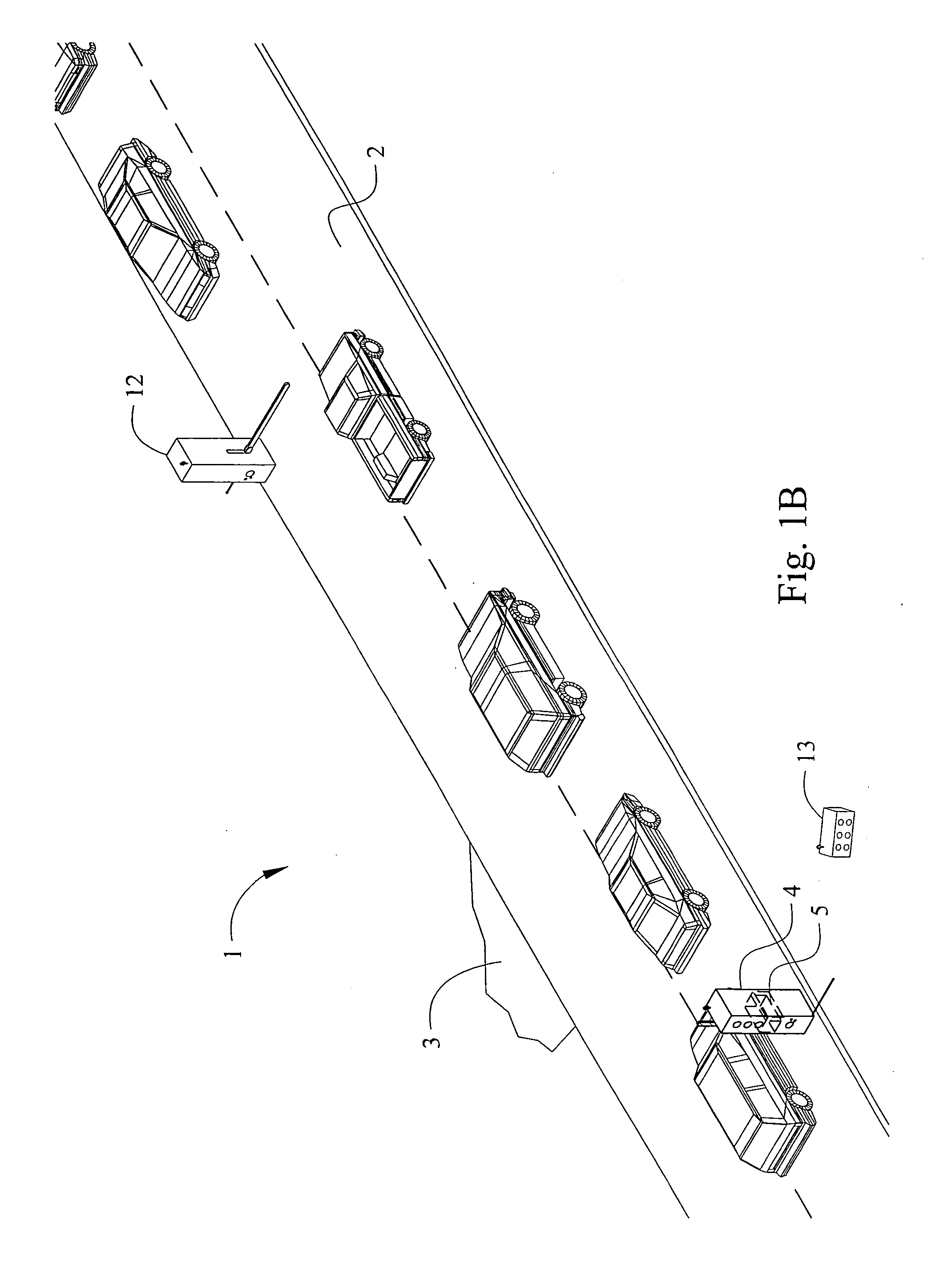
[0038] The present art overcomes the prior art limitations by providing an automated traffic control system 1 that counts and identifies passing vehicles. Vehicles encounter obstacles 3 such as construction upon roads around the world. In many cases, one lane 2 of traffic is allowed to pass the construction while traffic from the opposite direction waits. FIGS. 1A, 1B show traffic passing construction under the control of the present invention 1. The present invention 1 has a master unit 4, a slave unit 12, and a remote control 13. The master unit 4 differs from the slave unit 12 by having a computer 5 contained within. The handheld remote control 13 communicates with the master unit 4 to start, to stop, and to adjust the present invention 1. Each unit has an arm 8 to regulate the entry of traffic into a lane 2 past construction and the familiar red, yellow & green lights 7 to advise traffic passing the gate like arm 8 when the arm 8 will drop.

[0039]FIG. 2 shows a typical unit of t...


PUM


Abstract

The invention emulates the actions and decisions of flagmen to control and to expedite traffic along a single lane past construction. The invention has two portable traffic signal light units with arms. One unit has a computer that controls the system, three video cameras, and two way radio communication. The other unit has three video cameras and radio communication to the unit. A remote control is also provided for starting and stopping the system along with a manual override of the system. A coding feature restricts starting, and stopping the system to users of the remote control. The system also protects itself against vandalism and functions during periods of obscured vision.

Description

CROSS REFERENCE TO RELATED APPLICATION [0001] This non-provisional patent application claims priority to the provisional patent application 60 / 655,187 which was filed on Feb. 22, 2005 and is commonly owned by the same inventors.BACKGROUND OF THE INVENTION [0002] The automated traffic control system relates generally to automotive traffic signaling, and more specifically to optical driven signals for vehicles proximate to road construction. [0003] The present invention seeks to reduce the costs of flagmen and injuries to them near road construction or other hazards. Roads undergo construction and maintenance, and occasionally endure a vehicular accident. Motorists still use roads during construction and after some accidents, often sharing a road with oncoming traffic under control of one or more flagmen. The flagmen stop traffic in one direction and allow other traffic to proceed. Flagmen at each end of a construction site coordinate changes in the direction of traffic at time interv...

Claims


Application Information

Patent Timeline
Patent Type & Authority Applications(United States)
IPC IPC(8): G08G1/095G08B1/08E01F9/00
CPCG08G1/08G08G1/095
Inventor HAMMETT, JUANITA I.
Owner HAMMETT JUANITA I
Learn More