Blind slat structure

a technology for blind slats and slats, which is applied in the direction of shutters/movable grilles, door/window protection devices, constructions, etc., can solve the problems of uneconomically troublesome assembly, inflexible appearance, and damage to the appearance of blind slats, etc., to achieve convenient and rapid production of blind slats, economical efficiency, and versatile stylistic changes

Inactive Publication Date: 2006-09-07
CHING FENG BLINDS INC CO LTD
View PDF7 Cites 4 Cited by
  • Summary
  • Abstract
  • Description
  • Claims
  • Application Information

AI Technical Summary

Benefits of technology

[0004] It is, therefore, the primary purpose of the present invention to provide an improved blind slat structure, including a slat body and a pair of support members directly mounted to both elongate outer edges of the slat body thereon and securely fixed thereto via a connecting portion respectively, facilitating an easier and speedier production of the blind slat thereof to achieve the economical efficiency thereby.
[0005] It is, therefore, the second purpose of the present invention to provide an improved blind slat structure wherein, via the connecting portions thereof, the blind slat obtained thereby can not only provide versatile stylistic change to boost the visual effect thereof, but also refrain from the problem of furry edges in production to achieve a neat and beautiful look in display thereof.

Problems solved by technology

First, the slat body 10 is integrally made without any connecting portions disposed thereon for further decoration purpose and is prone to become defected with uneasily trimmed furry edges A formed in the production thereof which can easily destroy the look of the blind slat in display.
Second, the support members 12 thereof must be accommodated into the retaining spaces 11 of the slat body 10 therein respectively, which is uneconomically troublesome in assembly and inflexibly dull in appearance thereof.

Method used


Image

  • Blind slat structure
  • Blind slat structure
  • Blind slat structure

Examples


third embodiment

[0015] Please refer to FIG. 6 showing the present invention. The slat body 20 of the present invention can also have a pair of wrapping layers 23 symmetrically disposed at both elongate outer edges of one side surface thereon or alternatively arranged at the opposite elongate edges of the upper and lower side surfaces thereon respectively for retaining the support members 30 therein and securely fixed thereto via connecting portions 24 like seam lines 241.

fourth embodiment

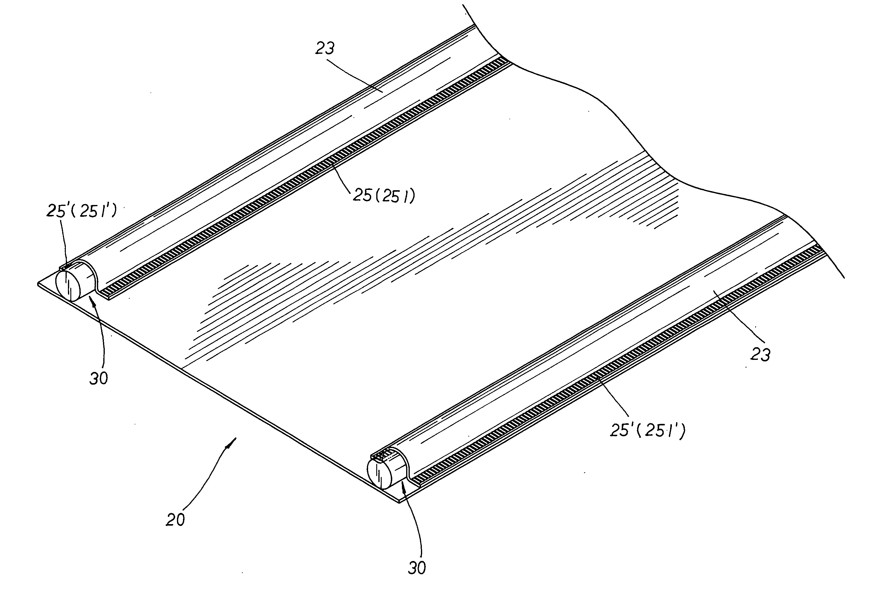
[0016] Please refer to FIG. 7 showing the present invention. The slat body 20 of the present invention can also have a pair of wrapping layers 23 symmetrically arranged at both elongate outer edges of one side surface thereon for retaining the support members 30 thereby wherein each of the wrapping layers 23 is securely fixed to the slat body 20 via a set of inner and outer connecting portions 25, 25′ made of inner / outer ultrasonic thermo welding lines 251, 251′ as shown in FIG. 7.

[0017] In addition, the connecting portions 21, 22, 24 and the inner / outer connecting portions 25, 25′ of the slat body 20 can be mad of adhesive agent 211, 221, seam threads / lines 212, 241, and ultrasonic thermo welding lines 251, 251′ thereof.


PUM


Abstract

An improved blind slat structure includes a slat body made of plastic materials, compound materials, glass fibers, and textile materials, and a pair of support members made of plastic materials, wood, compound materials and glass fibers symmetrically mounted to both elongate outer edges of the slat body thereon and securely fixed thereto via a connecting portion respectively, facilitating an easier and speedier manufacturing of the blind slat to achieve the economical efficiency thereof. Besides, via the connecting portions thereof, the blind slat obtained thereby can provide versatile stylistic change to boost the visual effect and achieve beautiful look in display thereof.

Description

BACKGROUND OF THE INVENTION [0001] The present invention is related to an improved blind slat structure, including a slat body and a pair of support members symmetrically mounted to both elongate outer edges of the slat body thereon and securely fixed thereto via a connecting portion respectively; whereby, the blind slat obtained thereby can provide versatile stylistic change to boost the visual effect and achieve beautiful look in display thereof. [0002] Please refer to FIG. 1. A conventional blind slat structure comprises a slat body 10 made of textile materials that is integrally woven into shape with a retaining space 11 formed at each elongate edge thereon for holding a support member 12 therein. [0003] However, the conventional blind slat structure above contains some disadvantages. First, the slat body 10 is integrally made without any connecting portions disposed thereon for further decoration purpose and is prone to become defected with uneasily trimmed furry edges A formed...

Claims


Application Information

Patent Timeline
Patent Type & Authority Applications(United States)
IPC IPC(8): E06B3/12E06B9/02E06B9/386
CPCE06B9/386
Inventor LIANG, WEN YING
Owner CHING FENG BLINDS INC CO LTD
Why Eureka
Try Eureka