
A Method For Determining The Condition Of An Object By Magnetic Resonance Imaging

a magnetic resonance imaging and object technology, applied in the field of method for determining the condition of an object by magnetic resonance imaging, can solve the problems of difficulty in performing and providing errors, and achieve the effect of enhancing the precision of the method and avoiding errors

Active Publication Date: 2006-08-17
ESAOTE
View PDF20 Cites 5 Cited by
  • Summary
  • Abstract
  • Description
  • Claims
  • Application Information

AI Technical Summary

Benefits of technology

[0031] Acquiring a sequence of three-dimensional images which can be stored as volumetric image data allows one to define and select section planes and regions of interests at a later time, without running the risk of having to repeat the acquisition process due to an imprecise or incorrect selection of the slices and / or of the regions of interest.
[0044] Furthermore the invention can be used for carrying out a follow-up, thus helping to recognize the way that the pathological condition develops or the way that the said pathological condition is regressing due, for example, to medical treatment.
[0066] It has been found that the above mentioned method allows one to determine the level of disease activity and the health condition of rheumatoid arthritis in patients by MRI perfusion measurements of the wrist and particularly of the synovial membrane. Indeed, the synovial membrane is the anatomical site where early inflammation can be detected. The method allows one to discriminate an active disease from an inactive disease and the level of activity.
[0068] Since the measurements relate to determining a mean intensity of the image along a selected region which is the entire region of interest or a selected part thereof and since the follow-up requires that imaging has to be carried out in different sessions at different times, it is important and critical that at each session the same slice or region of interest is selected. This can be very difficult to perform and can provide errors since the correct selection depends on the positioning of the wrist in the MRI scanner. Thus, using a three-dimensional MRI acquisition method and considering the mean intensity of an entire three-dimensional region of interest or of a three-dimensional part thereof, can be helpful in avoiding errors due to improper positioning and thus to the selection of an incorrect section plane or an incorrect region of interest. Further providing markers either of the external kind or consisting in precise anatomical or morphological particulars of the anatomical region under examination, and combining the markers with the above-mentioned registration methods and algorithms allows one to enhance the precision of the method also in combination with the three-dimensional MRI acquisition.

Problems solved by technology

This can be very difficult to perform and can provide errors since the correct selection depends on the positioning of the wrist in the MRI scanner.

Method used


Image

  • A Method For Determining The Condition Of An Object By Magnetic Resonance Imaging
  • A Method For Determining The Condition Of An Object By Magnetic Resonance Imaging
  • A Method For Determining The Condition Of An Object By Magnetic Resonance Imaging

Examples


Embodiment Construction

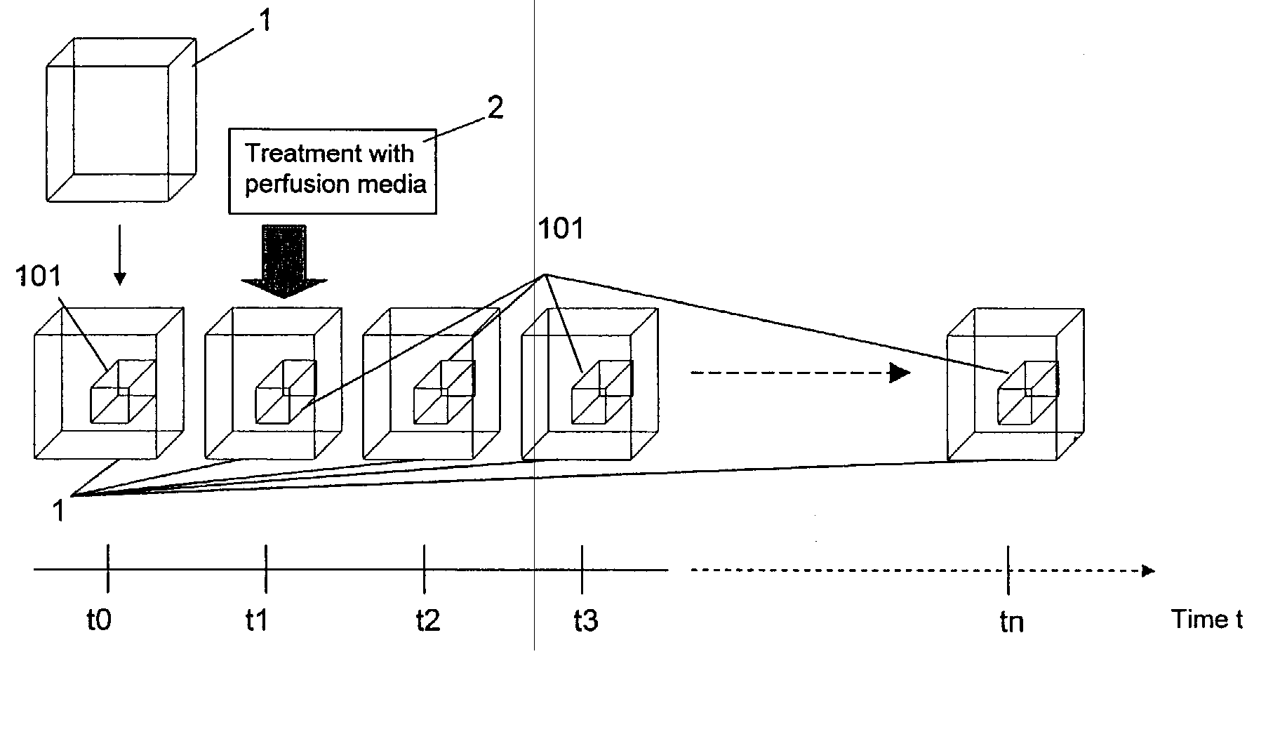
[0079] Relating to FIG. 1, an object 1 is represented by a cube. The object 1 is positioned in an MRI scanner and one or more panoramic images are acquired, the so-called “scout images”. If needed, these images are used by the operator to select a certain particular region of the object 1, a so-called “region of interest” (ROI) indicated by a small cube 101 within the object 1.

[0080] Thus, the apparatus is ready to carry out a sequence of images of the same region of interest 101 at different times.

[0081]FIG. 1 illustrates the sequence of imaging acquisitions along a time axis t by reproducing the image of the object 1 and of the region of interest 101 at each acquisition time ti, where i=0,1,2,3, . . . ,n.

[0082] The object 1 under examination can show spontaneous time varying states which are typical for a certain condition of the object. If this is not the case, a time varying state can be induced in the object under examination 1 and more precisely in the region of interest by...


PUM


Abstract

A method for determining the condition of an animate or inanimate object by magnetic resonance imaging, MRI, particularly for determining the pathologic condition of rheumatoid arthritis (“arthritis rheumatoides”) and carrying out a patient follow-up.

Description

FIELD OF THE INVENTION [0001] The present invention relates to a method for determining the condition of an animate or an inanimate object by MRI. BACKGROUND OF THE INVENTION [0002] The present invention particularly relates to a method for determining the condition of an animate or an inanimate object which condition can be evaluated by providing information on time dependent effects which are either induced or spontaneous. For example, in a solid body which is not of a biological type, the perfusion of a gas or a liquid which is fed under certain condition can be observed by MRI, such as by acquiring a sequence of images in which each image is acquired at a different time within a certain time period. Structural modifications relating to a change in physical or chemical parameters can be observed, such as, for example, temperature dependent structural changes in solid bodies which are subjected to temperature which varies over time by heating or by cooling or structural changes wh...

Claims


Application Information

Patent Timeline
Patent Type & Authority Applications(United States)
IPC IPC(8): A61B5/05
CPCA61B5/055A61B5/4528G01N24/08G01R33/56308A61B5/0037
Inventor BIGLIERI, EUGENIOSATRAGNO, LUIGI
Owner ESAOTE
Learn More