Child bouncing apparatus

Inactive Publication Date: 2006-08-17
DOUGLAS TAMMY G
View PDF21 Cites 7 Cited by
  • Summary
  • Abstract
  • Description
  • Claims
  • Application Information

AI Technical Summary

Benefits of technology

[0006] It is therefore an object of the present invention to provide a stable and sturdy child's bouncing apparatus for use by young children to develop body muscular strength and body movement coordination.
[0008] Still another object of the present invention is to provide a bouncing apparatus in accordance with the preceding objects which enables an occupant to place his feet on the footrests at a mid-portion of the support strut and to grasp the handles at the upper end of the support strut and move in a repetitive manner between a generally vertical standing position and a sitting position in which the ball is partially compressed with the compressed air inside of the ball exerting an upward force to assist the occupant in moving from the sitting position to the generally vertical standing position.
[0010] A further object of the present invention is to provide a child's bouncing apparatus in which the rigid supporting strut having the footrests and handles thereon is rigidly connected with the supporting base for positioning the handles and footrests adjacent to the ball.
[0011] Still a further object of the present invention is to provide a child's bouncing apparatus that serves as a bouncing toy with repetitive movement of the child using the device to entice the child to use the device for long periods of time thereby serving as an exercise device to develop muscles and also to develop coordination of various body components.
[0012] A final object of the present invention recited herein is to provide a child's bouncing apparatus which can be made from readily available and inexpensive components for ease and economy of manufacture and which will be sturdy and long lasting in operation and use.

Problems solved by technology

The direction of movement of the ball during bouncing movement, however, is unpredictable and thus requires considerable skill by the user to maintain his / her position on the ball during bouncing movement.

Method used


Image

  • Child bouncing apparatus
  • Child bouncing apparatus
  • Child bouncing apparatus

Examples


Embodiment Construction

[0019] Although only one preferred embodiment of the invention is explained in detail, it is to be understood that the invention is not limited in its scope to the details of construction and arrangement of components set forth in the following description or illustrated in the drawings. The invention is capable of other embodiments and of being practiced or carried out in various ways. Also, in describing the preferred embodiments, specific terminology will be resorted to for the sake of clarity. It is to be understood that each specific term includes all technical equivalents which operate in a similar manner to accomplish a similar purpose.

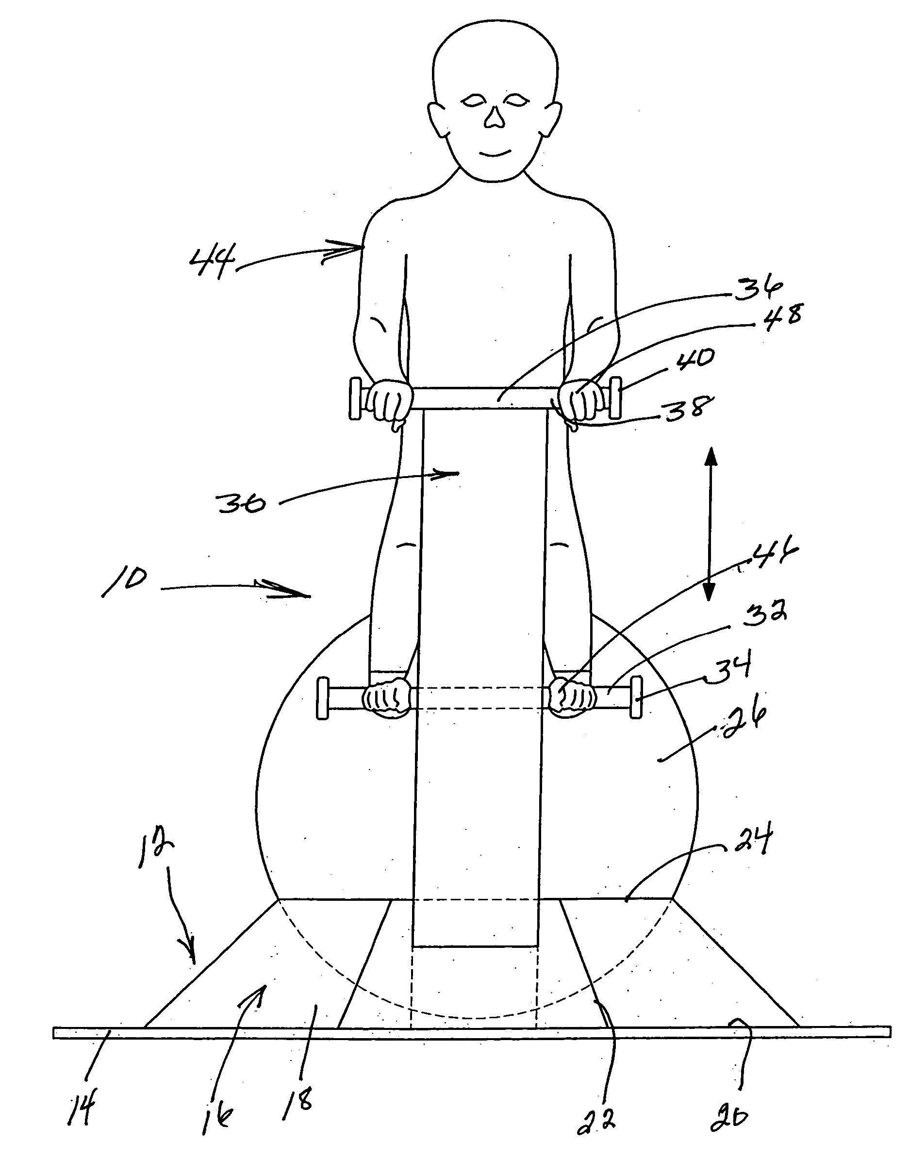
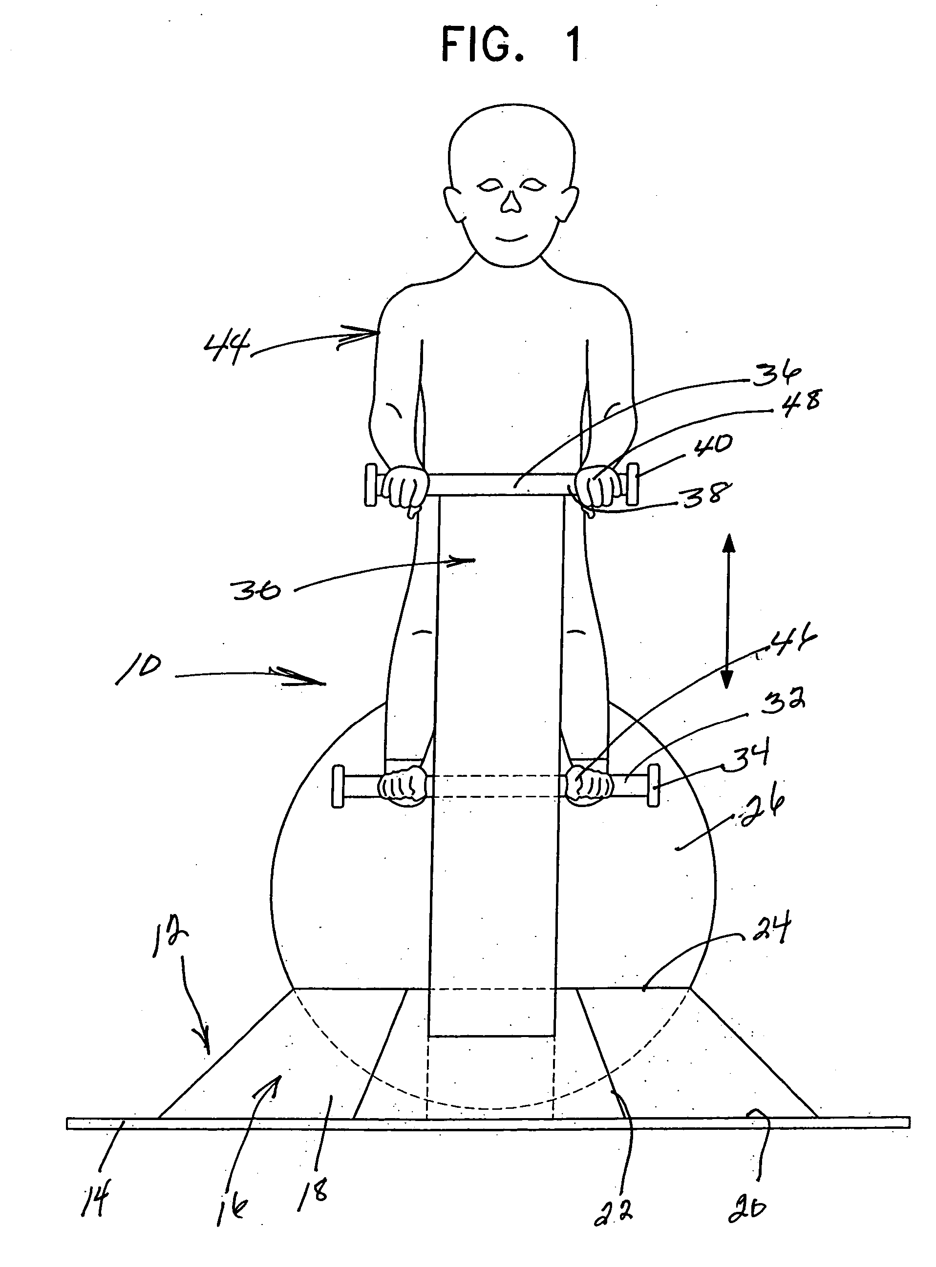
[0020] The child's bouncing apparatus of the present invention is generally designated by reference numeral 10 and includes a supporting base, generally designated by reference numeral 12. Base 12 includes a bottom panel or plate 14 that can be supported on a generally flat surface such as the floor or other like surface. The bottom plate 14 m...


PUM


Abstract

A child's bouncing apparatus includes a supporting base having an upwardly opening cavity receiving and positioning a portion of the periphery of a large inflated flexible ball. A rigid structure extends upwardly alongside the periphery of the ball positioned in the base. The rigid structure includes laterally extending footrests at a mid-portion and laterally extending handles or handgrips at the upper end. A child occupying the bouncing apparatus engages his feet with the footrests and his hands with the handgrips and moves between a vertically standing position and a sitting position on the ball with the weight of the child partially compressing the upper periphery of the ball downwardly. The downward compression provides an upward thrust to the child during a repetitive movement between the standing position and the sitting position.

Description

BACKGROUND OF THE INVENTION [0001] 1. Field of the Invention [0002] The present invention generally relates to a child's bouncing apparatus and more specifically to a child's bouncing apparatus having a supporting base with an upwardly opening cavity receiving and positioning a portion of the periphery of a large inflated ball on which the child can bounce. [0003] 2. Description of the Related Art [0004] Various types of bouncing toys, including an inflatable resilient member of various shapes and configurations, are well known in the prior art. Such prior art toys include spherical inflated resilient balls having a handle incorporated at an upper periphery thereof in which the lower portion of the ball merely rests upon a floor surface or the like. The direction of movement of the ball during bouncing movement, however, is unpredictable and thus requires considerable skill by the user to maintain his / her position on the ball during bouncing movement. Also known is a supporting base...

Claims


Application Information

Patent Timeline
IPC IPC(8): A47C7/02
CPCA63B5/00A63B41/00A63B2208/12A63B2225/62A63B41/125
Inventor DOUGLAS, TAMMY G.
Owner DOUGLAS TAMMY G
Why Eureka
Try Eureka