Image forming apparatus

Inactive Publication Date: 2006-08-10
SEIKO EPSON CORP
View PDF8 Cites 34 Cited by
  • Summary
  • Abstract
  • Description
  • Claims
  • Application Information

AI Technical Summary

Benefits of technology

[0012] For highly accurate color misregistration correction based on position information regarding registration marks in an image forming apparatus of the tandem type, the accuracy of detecting registration marks is important. However, the conventional techniques do not consider this sufficiently but merely use strip-like solid images as registration marks, thereby deteriorating the detection accuracy because of the so-called edge effect. To be more specifically, when two-dimensional solid images are formed in the manner described above, toner particles get concentrated particularly in edge portions of registration marks due to the edge effect. This locally enhances the density of toner in the edge portions of the registration marks and greatly varies an output signal from an optical sensor. The accuracy of detecting the registration marks based on the output signal from the optical sensor consequently decreases, leading to a problem that it is not possible to correct a color misregistration favorably and therefore printing proceeds with the color misregistration uncorrected or desired hues are not obtained.
[0015] The invention has been made in light of these problems, and accordingly, aims at providing an image forming apparatus which is capable of forming registration marks while suppressing the edge effect, and hence, preventing a color misregistration, deteriorated hues, etc.
[0016] Further, the invention aims at providing an image forming apparatus which is capable of suppressing a deterioration of the position detecting accuracy of detecting registration marks due to a change of the environment such as a temperature change, and hence, preventing a color misregistration, deteriorated hues, etc.
[0017] Still further, the invention aims at providing an image forming apparatus which is capable of improving the elasticity of an intermediate transfer belt, and hence, forming a favorable image.

Problems solved by technology

However, the conventional techniques do not consider this sufficiently but merely use strip-like solid images as registration marks, thereby deteriorating the detection accuracy because of the so-called edge effect.
The accuracy of detecting the registration marks based on the output signal from the optical sensor consequently decreases, leading to a problem that it is not possible to correct a color misregistration favorably and therefore printing proceeds with the color misregistration uncorrected or desired hues are not obtained.
However, the conventional techniques do not consider this sufficiently but merely use strip-like solid images as registration marks.
Such a change of the toner density in the edge portions is particularly problematic during position detection relied upon detection of the edge portions of the registration marks described above.
A change of the toner density associated with a change of the environment such as a temperature change thus deteriorates the position detecting accuracy of detecting the registration marks based on the output signal from the optical sensor, which may form a problem that color misregistration correction is not performed favorably and printing proceeds with the color misregistration uncorrected or desired hues are not obtained.
In the apparatus wherein a PC resin is used as the belt base material of an intermediate transfer belt, the intermediate transfer belt may be inferior in terms of the elasticity and transfer of a toner image may fail.
Further, a color image forming apparatus of the tandem type may have the following problems.
However, since the intermediate transfer belt in which a PC resin is used as the belt base material is inferior in terms of the elasticity, detection of the registration marks transferred onto the intermediate transfer belt may fail.
Upon failed detection of defects, the position detecting accuracy of detecting the registration marks drops down, leading to a problem that it is not possible to perform color misregistration correction favorably and therefore printing proceeds with the color misregistration uncorrected or a problem that desired hues are not obtained.

Method used


Image

  • Image forming apparatus
  • Image forming apparatus
  • Image forming apparatus

Examples


first embodiment

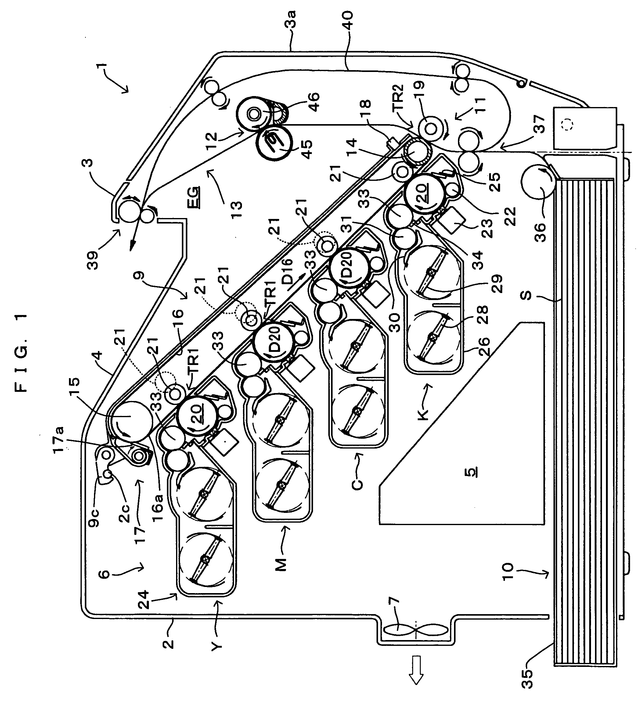
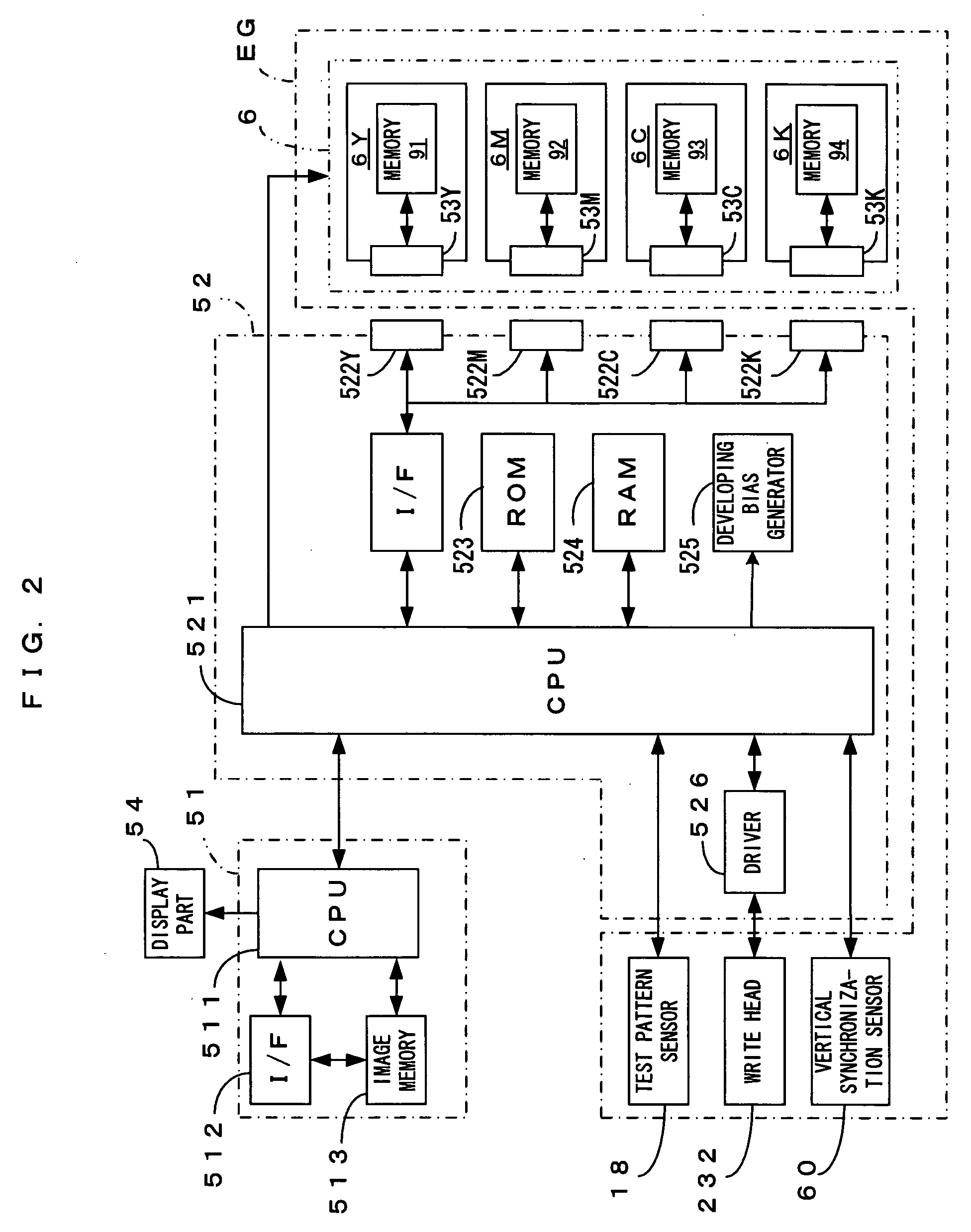
[0048]FIG. 1 is a drawing which shows an embodiment of an image forming apparatus according to the present invention. FIG. 2 is a block diagram which shows an electric structure of the image forming apparatus of FIG. 1. The image forming apparatus 1 is an image forming apparatus which selectively executes color printing of superimposing toner (developing agents) in four colors of black (K), cyan (C), magenta (M) and yellow (Y) and accordingly forming a full-color image or monochromatic printing of forming a monochrome image using only black (K) toner. In the image forming apparatus 1, as a main controller 51 receives an image formation command (print command) from an external apparatus such as a host computer, an engine controller 52 controls respective parts of an engine part EG in accordance with a command from the main controller 51, a predetermined image forming operation is executed, and an image corresponding to the image formation command is formed on a sheet (recording mater...

second embodiment

[0086]FIG. 11A and FIG. 11B is a drawing which shows operations of the image forming apparatus which is shown in FIG. 1 according to the second embodiment. This apparatus executes the color misregistration correction which utilizes registration marks at appropriate timing which may be power-on, cartridge exchange or the like. To be more specific, the CPU 521 of the engine controller 52 controls the respective portions of the apparatus in accordance with a program stored in the ROM 523 regarding the color misregistration correction, whereby registration marks are formed and detected and the color misregistration correction is executed in the following manner.

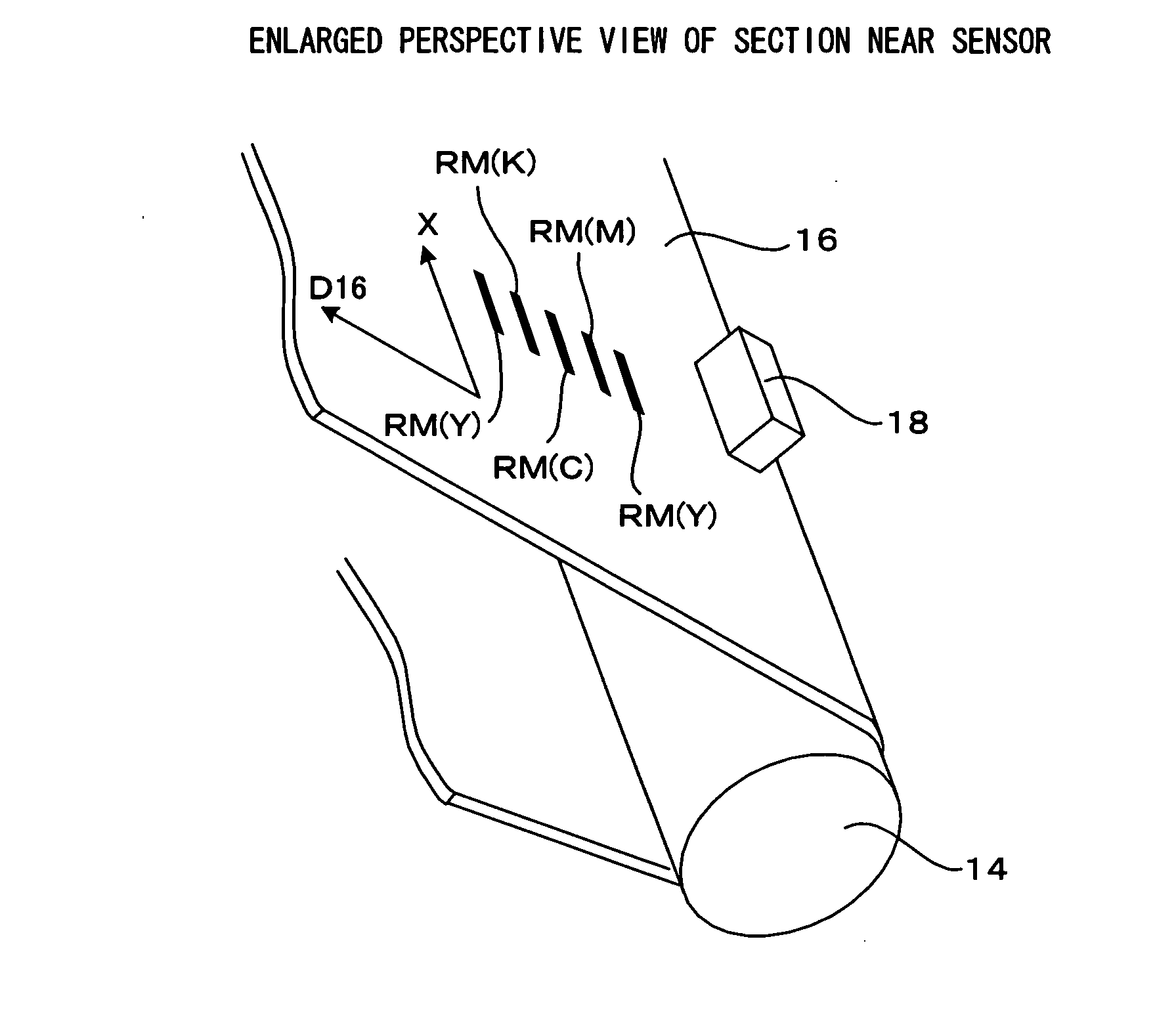
[0087] First, in response to a control command from the CPU 521 of the engine controller 52, the image forming stations Y, M, C and K form, as registration marks RM, halftone toner images formed by two-dimensional halftone patterns of plural lines which extend along the main scanning direction which is orthogonal to the transpor...

third embodiment

[0092] Detection of edge portions of registration marks RM realizes detection of the registration marks RM in the second embodiment as described earlier, whereas the third embodiment requires detecting upstream edge portions of registration marks RM taken along the transporting direction D16. That is, a piece of position information regarding each registration mark RM is detected based on a change of the output signal from the test pattern sensor (optical sensor) 18 which occurs as an upstream portion of the registration mark RM along the transporting direction D16 moves passed the test pattern sensor (optical sensor) 18, and the color misregistration correction is executed based on these pieces of position information. Further, as shown in FIG. 14A, a halftone toner image forming each registration mark RM consists of a linear pattern LP1 extending along the main scanning direction X which is approximately orthogonal to the transporting direction D16 and any desired two-dimensional ...


PUM


Abstract

A registration mark is a toner image which has a first linear pattern and a second linear pattern, which extend along a main scanning direction, and a two-dimensional pattern. The first linear pattern, the two-dimensional pattern and the second linear pattern are arranged apart from each other in this order along a transporting direction. In short, the linear patterns and extending along the main scanning direction are formed spaced apart from the two-dimensional pattern, one toward the upstream side and the other toward the downstream side, along the transporting direction. This suppresses the edge effect along the transporting direction and realizes accurate detection of the position of each registration mark by a test pattern sensor.

Description

CROSS REFERENCE TO RELATED APPLICATION [0001] The disclosure of Japanese Patent Applications enumerated below including specification, drawings and claims is incorporated herein by reference in its entirety: [0002] No.2005-001468 filed Jan. 6, 2005; [0003] No.2005-004296 filed Jan. 11, 2005; and [0004] No.2005-005556 filed Jan. 12, 2005. BACKGROUND OF THE INVENTION [0005] 1. Field of the Invention [0006] The present invention relates to an image forming apparatus in which toner images formed by an image former are transferred onto an intermediate transfer medium which moves in a predetermined direction and the toner images are temporarily carried. [0007] 2. Description of the Related Art [0008] The apparatus described in JP-A-2004-109617 for example is known as an image forming apparatus of this type. In this image forming apparatus an image forming station, in which a charger, an image writer and a developer are disposed around a latent image carrier such as a photosensitive drum, ...

Claims


Application Information

Patent Timeline
IPC IPC(8): G03G15/01
CPCG03G15/1685G03G15/0194G03G2215/0161G03G2215/0132
Inventor KAWADA, KUNIHIRONOMURA, YUJIROIKUMA, KEN
Owner SEIKO EPSON CORP
Why Eureka
Try Eureka