
Method and apparatus for alignment, comparison & identification of characteristic tool marks, including ballistic signatures

a technology of characteristic tool marks and alignment methods, applied in the field of method and apparatus for alignment, comparison & identification of characteristic tool marks, including ballistic signatures, can solve the problems of not using infrared images for this comparison test, and achieves the effects of minimizing training and time, easy to clean up debris, and little eviden

Inactive Publication Date: 2006-08-10
PROKOSKI FRANCINE J
View PDF14 Cites 60 Cited by
  • Summary
  • Abstract
  • Description
  • Claims
  • Application Information

AI Technical Summary

Benefits of technology

[0070] The weapon itself should display identifying information such as the manufacturer's name and logo and serial number. If the serial number has been removed, use of infrared imaging can assist in recovering the information, since the emissivity of the area will be affected by attempts to file off or chemically etch off the serial number. By heating and cooling the weapon, a number of corresponding but different images can be obtained and all used to assist the reconstruction effort.
[0140] 7. Holder for gun which facilitates operation of an infrared probe which has a helical scanning rotating head and forms an infrared image of the inside of the barrel of a gun as it cools.

Problems solved by technology

Therefore, no infrared images were obtained or used for this comparison test.

Method used


Image

  • Method and apparatus for alignment, comparison & identification of characteristic tool marks, including ballistic signatures
  • Method and apparatus for alignment, comparison & identification of characteristic tool marks, including ballistic signatures
  • Method and apparatus for alignment, comparison & identification of characteristic tool marks, including ballistic signatures

Examples


Embodiment Construction

—USING INFRARED IMAGES TO REFINE VISIBLE IMAGE DETAILS FOR BALLISTICS IDENTIFICATION IMAGE AND INFORMATION CAPTURE

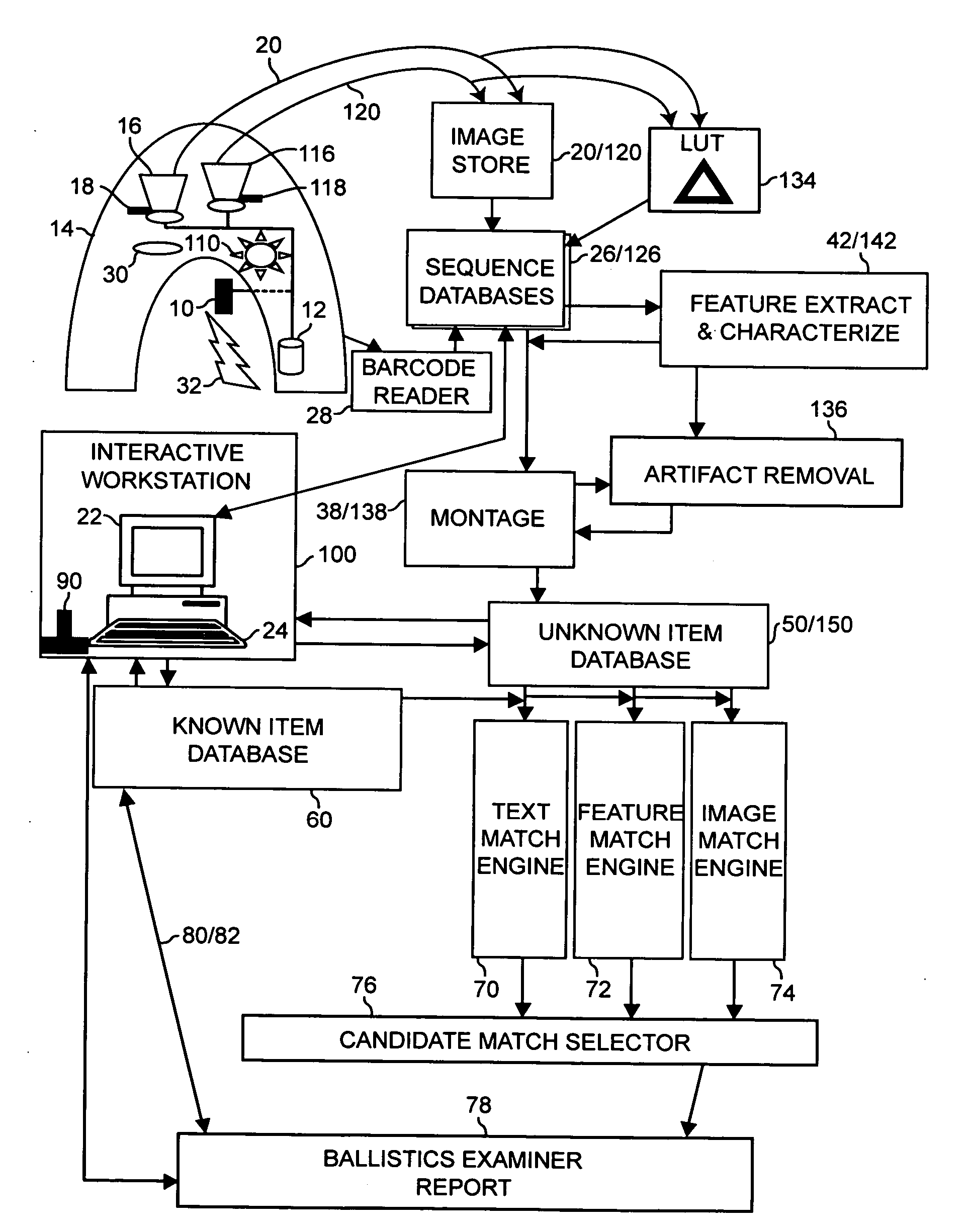
[0167] A ballistic item 10 is placed in a holder 12 and surrounded by a shroud 14 covering it and an infrared camera 16 such that external lighting and heating sources are blocked. The camera focus mechanism 18 is varied over a range such that all details of the infrared image of the ballistic item are clearly captured in a sequence of infrared images 20.

[0168] Optionally, one or more spectral filters 30 can be installed and additional sequences of infrared images obtained. Optionally, a heater 32 can be used to raise the temperature of the ballistic item and additional sequences of infrared images obtained for the item at the elevated temperature and as it cools.

[0169] A controlled light source 110 is then turned on to illuminate the ballistic item and a video camera 116 is used to produce a sequence of visible images 120 by varying the focus mechanism 118.

[0170] Eac...


PUM


Abstract

Systematic use of infrared imaging characterizes marks made on items and identifies the particular marking tool with better accuracy than use of visual imaging. Infrared imaging performed in total darkness eliminates shadows, glint, and other lighting variations and artifacts associated with visible imaging. Although normally used to obtain temperature measurements, details in IR imagery result from emissivity variations as well as thermal variations. Disturbing an item's surface texture creates an emissivity difference producing local changes in the infrared image. Identification is most accurate when IR images of unknown marks are compared to IR images of marks made by known tools. However, infrared analysis offers improvements even when only visual reference images are available. Comparing simultaneous infrared and visual images of an unknown item, such as bullet or shell casing, can detect illumination-induced artifacts in the visual image prior to searching the visual database, thereby reducing potential erroneous matches.

Description

[0001] This application is a continuation of, and claims priority from, co-pending U.S. patent application Ser. No. 09 / 329,217 of the same title, which in turn claims priority from U.S. Provisional Patent Application No. 60 / 087,512 filed Jun. 10, 1998.SUBJECT OF THE PATENT [0002] The method and apparatus of this patent involve tool mark identification, which is a type of forensic analysis aimed at comparing images of marks made on an item with images of marks stored in a database to find any which appear similar enough that they could have been made by the same tool. The principal purpose is to find linkage between items associated with crimes, to assist in solving the crimes. The primary application is for analysis of ballistic items, which includes guns, bullets, and shell casings. BACKGROUND OF THE INVENTION [0003] Guns, including pistols, revolvers, semiautomatics, rifles, and shotguns are used in the commission of thousands of crimes per day throughout the country. There is gro...

Claims


Application Information

Patent Timeline
Patent Type & Authority Applications(United States)
IPC IPC(8): G06K9/00
CPCF42B35/00G06T7/0002G06T2207/30108
Inventor PROKOSKI, FRANCINE J.
Owner PROKOSKI FRANCINE J
Learn More