Winding stem positioning plate-like structural body and electronic timepiece possessing the same

a technology of positioning plate and structure, which is applied in the direction of electric winding, instruments, and horology, can solve the problems of poor utilization efficiency of narrow space in timepiece cases, and low degree of freedom, so as to simplify the shape of spring parts, simple structure of battery plus terminal, and easy manufacture

Inactive Publication Date: 2006-08-10
SEIKO INSTR INC
View PDF5 Cites 3 Cited by
  • Summary
  • Abstract
  • Description
  • Claims
  • Application Information

AI Technical Summary

Benefits of technology

[0019] In an electronic timepiece possessing a winding stem positioning structural body of the present invention, the base body part possesses in its one end a battery pushing plate spring part for pushing a battery, and possesses in its the other end a crystal oscillator case body pushing plate spring part for pushing a crystal oscillator case body. By this, not only a large crystal oscillator and the battery among timepiece components can be certainly pushed but also a retention of the base body part of the winding stem positioning structural body can be more stably performed. Incidentally, typically, the winding stem positioning plate-like structural body consists of a metal-made plate spring, and functions as a battery plus terminal. Accordingly, it becomes a simple structure of the battery plus terminal, and its manufacture becomes easy as well.
[0020] Further, in an electronic timepiece possessing a winding stem positioning structural body of the present invention, typically, the plate-like structural body possesses a reset lever biasing spring part for biasing a reset lever to a reset position in one end edge in the thickness, direction of the timepiece main body. In this case, it becomes possible to form the reset lever practically by a rigid body. Further, in this case, from the fact that the reset lever biasing spring part extends in a direction (typical pe...

Problems solved by technology

However, a conventional winding stem positioning structural body of this kind, since it is necessary to cause one part of the plate-like part which has spreaded along the extension face of the machine casing to function as the plate spring, it is necessary to comparatively, largely ensure a space that a deformation of the plate spring requires for bending in the ...

Method used


Image

  • Winding stem positioning plate-like structural body and electronic timepiece possessing the same
  • Winding stem positioning plate-like structural body and electronic timepiece possessing the same
  • Winding stem positioning plate-like structural body and electronic timepiece possessing the same

Examples


Embodiment Construction

[0029] Next, one preferred implementation mode of the present invention is explained on the basis of one preferred embodiment shown in the appended drawings.

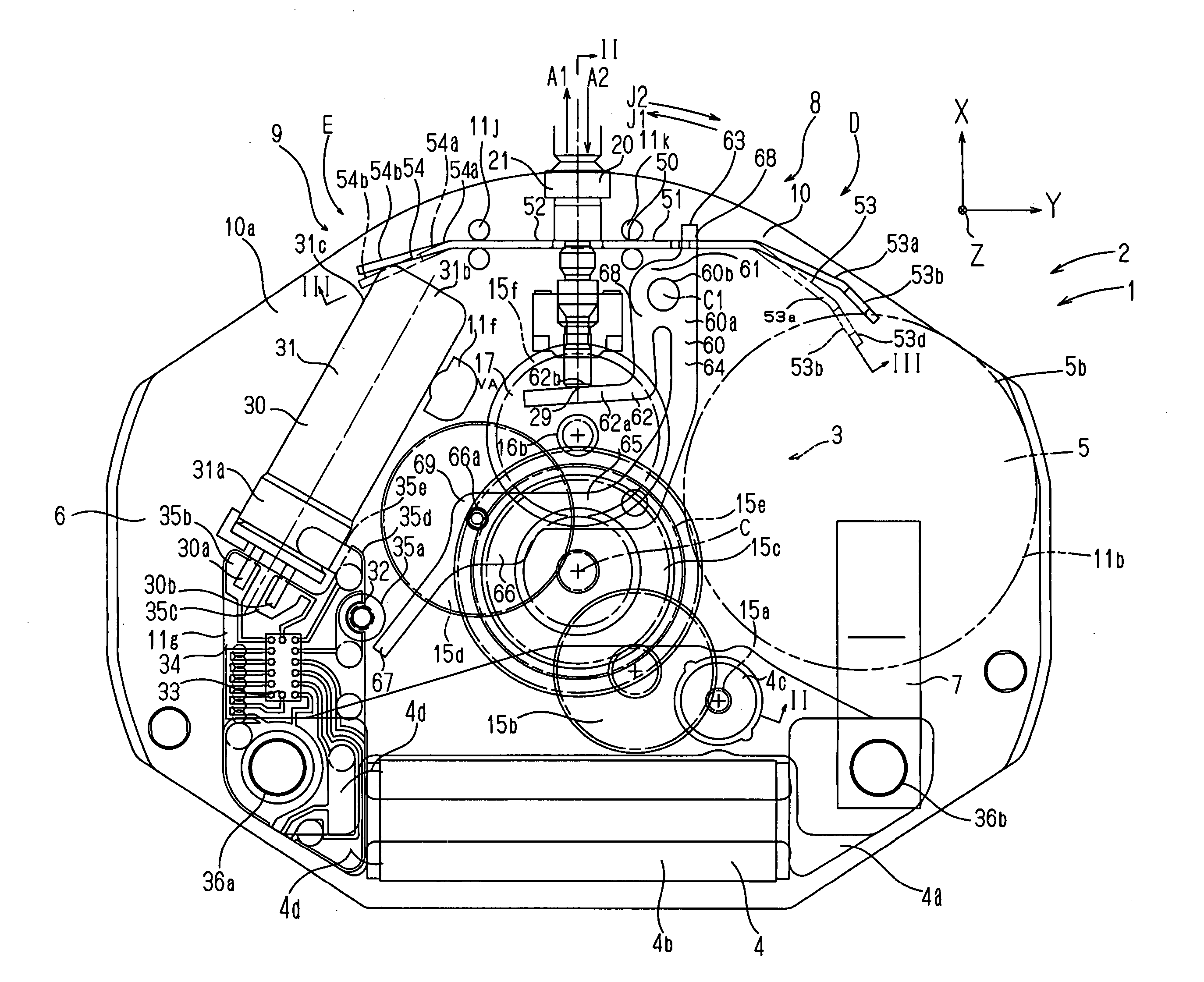
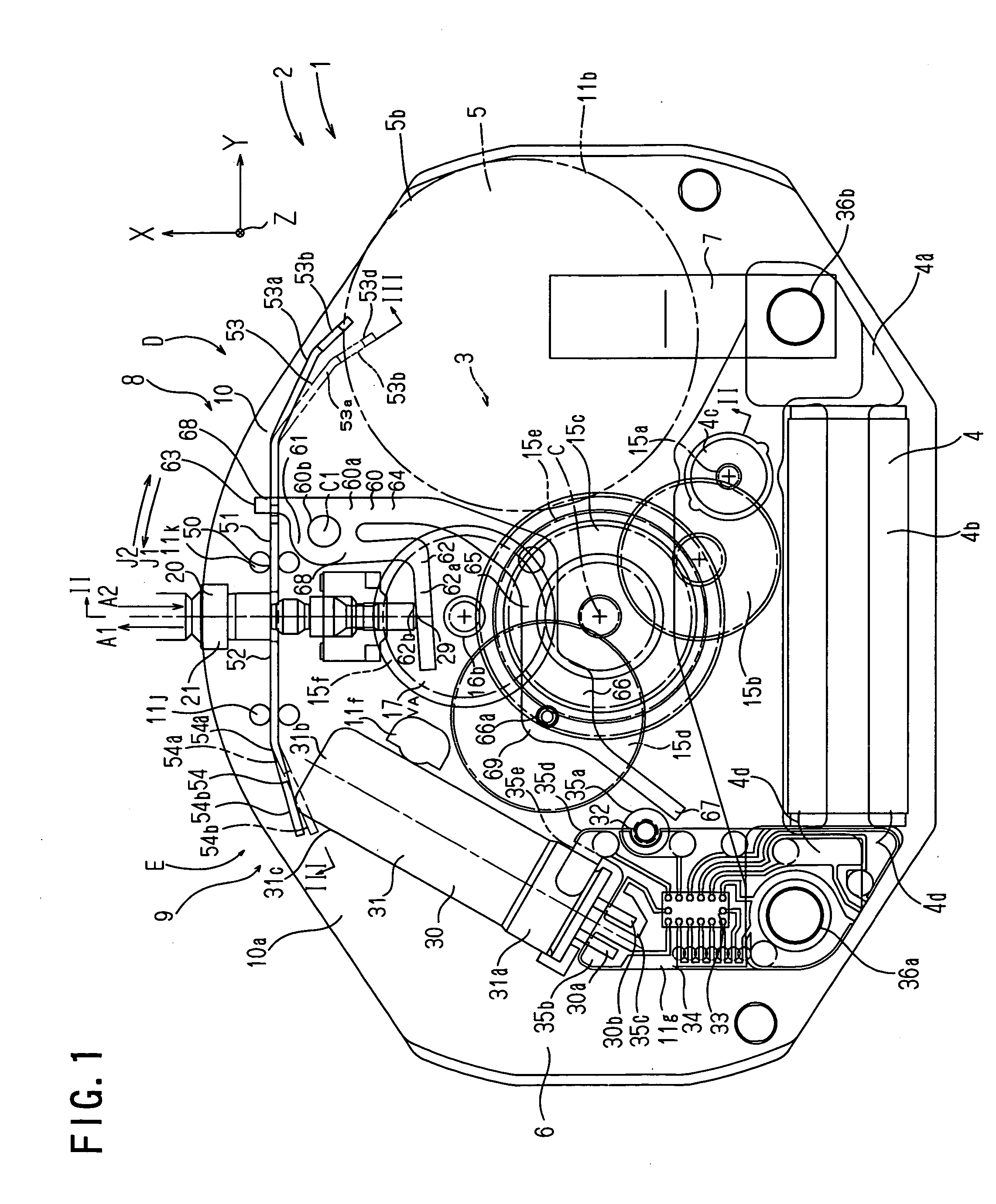
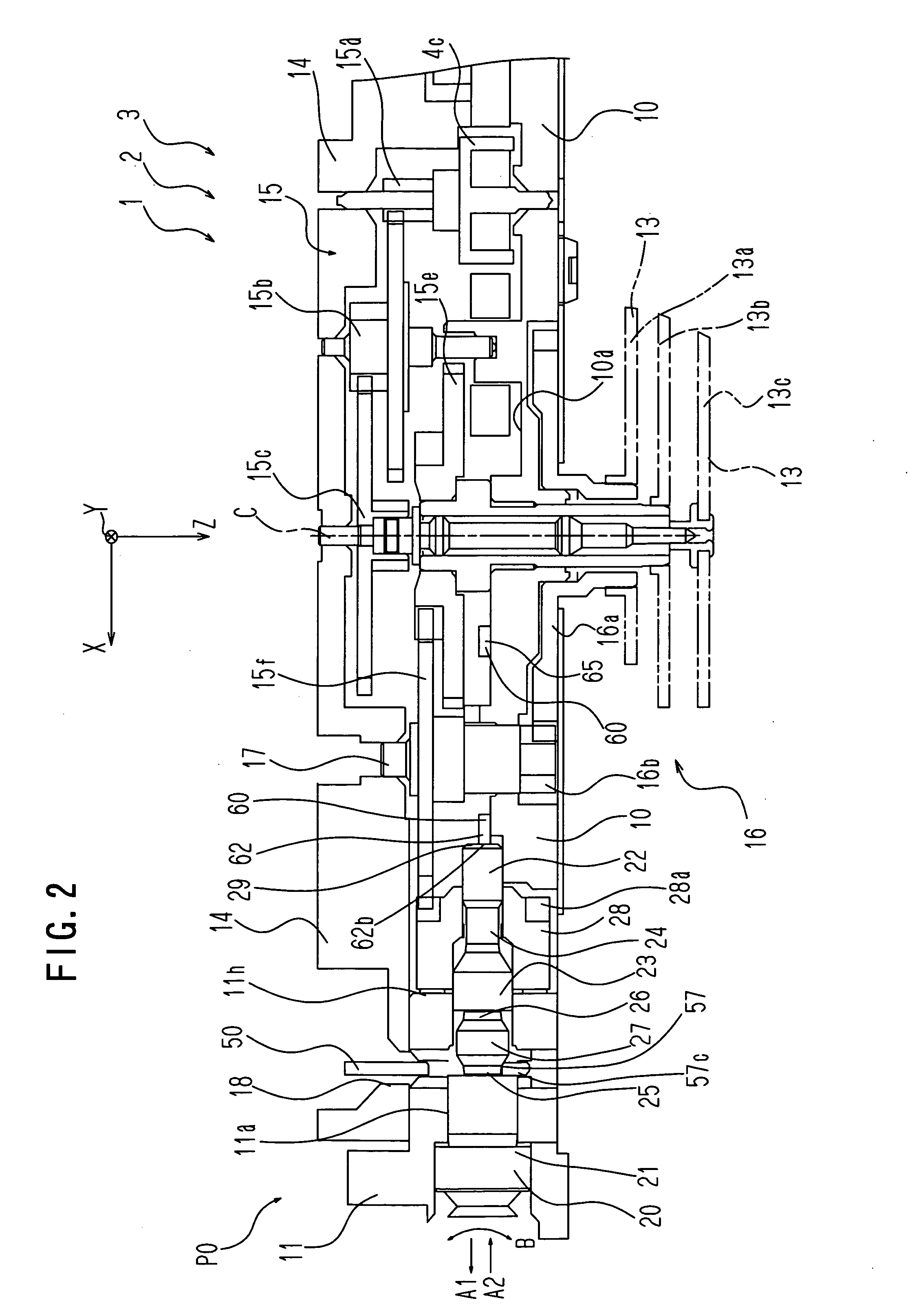
[0030] A timepiece main body 2 of an electronic timepiece 1 possesses a main plate 10 constituting a machine casing. Hereunder, for a simplification of the explanation, there is adopted a three-dimensional orthogonal coordinate system fixed to the main plate 10. Here, a pulling-out direction A1 (3 o'clock side) of a winding stem 20 is made an X direction, a right direction (12 o'clock side) in FIG. 1 is made a Y direction, and a direction deep in the drawing and perpendicular to the drawing is made a Z direction. The Z direction coincides with a side where a dial 12 (refer to FIG. 2) exists. Here, an XY plane is parallel to a main face of the timepiece main body 2, and the direction of a Z axis is a direction perpendicular to the main face of the timepiece main body 2. In FIG. 11 and FIG. 2, C is a rotation center axis of time ...


PUM


Abstract

To provide a winding stem positioning plate-like structural body capable of suppressing an occupation space to a lowest limit, and an electronic timepiece possessing the same. A winding stem positioning plate-like structural body of an electronic timepiece 1 has a plate-like base body part which is disposed to a machine casing of a timepiece main body under a state that its main face forms an angle with a main face of the timepiece main body, and which is held by an engaging part of the machine casing of the timepiece main body, and an elastic winding stem engaging arm part which extends from one end edge in a thickness direction of the machine casing within the base body part to the thickness direction of the timepiece main body and an extension direction of the main face of the timepiece main body, which engages with a small diameter axle part adjoining a bead-like part of a winding stem in a winding stem engaging part of a tip, and which allows a transit of the bead-like part 27 by being elastically deformed in an F2 direction by the bead-like part when the winding stem is put in and out in A1, A2 directions.

Description

BACKGROUND OF THE INVENTION [0001] 1. Field of the Invention [0002] The present invention relates to a winding stem positioning plate-like structural body, and an electronic timepiece possessing the same. [0003] 2. Description of the Prior Art [0004] It is known to make such that, when pulling out a winding stem in order to rotate a hand and when thereafter pushing the winding stem, a positioning of the winding stem is performed and a click feeling is given to a user. It is also known to make such that that, for this positioning of the winding stem and this bestowal of the click feeling, a bead-like large diameter part is formed in the winding stem, an engagement part is elastically engaged with a small diameter part located adjacently to the bead-like large diameter part and, when the winding stem is put in and out, the engagement part is relatively moved from the small diameter part, in one end side, of the bead-like part to the small diameter part in the other end side beyond the...

Claims


Application Information

Patent Timeline
IPC IPC(8): G04B29/00
CPCG04C3/008
Inventor ONO, TAMOTSU
Owner SEIKO INSTR INC
Why Eureka
Try Eureka