
Sun visor for vehicle

a technology for sun visors and vehicles, applied in the direction of roofs, superstructures, monocoque constructions, etc., can solve the problems of increasing the overall size of the sun visor and the receiving portion of the shaft, and achieve the effect of attenuating the impact energy

Active Publication Date: 2006-08-10
HONDA MOTOR CO LTD +1
View PDF3 Cites 13 Cited by
  • Summary
  • Abstract
  • Description
  • Claims
  • Application Information

AI Technical Summary

Benefits of technology

[0011] It is therefore an object of this invention to provide a sun visor for a vehicle in which the impact is distributed or divided with time, thereby positively preventing withdrawal of a shielding member.
[0014] In the invention of claim 1, when the sun visor is mounted on the vehicle, the projections of the shaft can not pass through the passage portions of the bearing member, and therefore the shielding member will not be easily withdrawn or disengaged from the shaft. And besides, the timings at which the projections of the shaft abut respectively against the retaining portions of the bearing members can be staggered, and therefore the impact can be distributed or divided with time, and the projections of the shaft are sequentially brought into abutting engagement with the respective retaining portions of the bearing member, while attenuating the energy of the impact. Therefore, the shielding member can be positively prevented from being withdrawn or disengaged from the shaft.

Problems solved by technology

In the sun visor of Patent Literature 1, however, there is provided only one retaining projection, and therefore in order to secure a sufficient strength to positively prevent the disengagement of the shielding plate, the retaining projection must be increased in size, and as a result there is encountered a problem that the shaft receiving portion has an increased size, so that the overall size of the sun visor increases.

Method used


Image

  • Sun visor for vehicle
  • Sun visor for vehicle
  • Sun visor for vehicle

Examples


Embodiment Construction

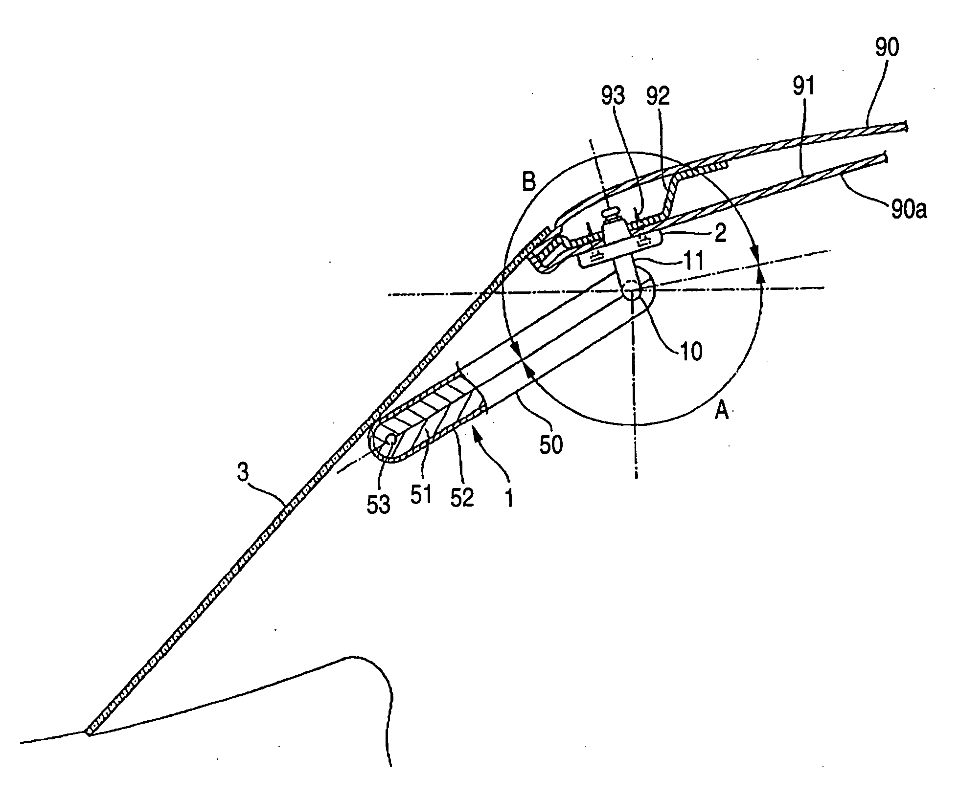
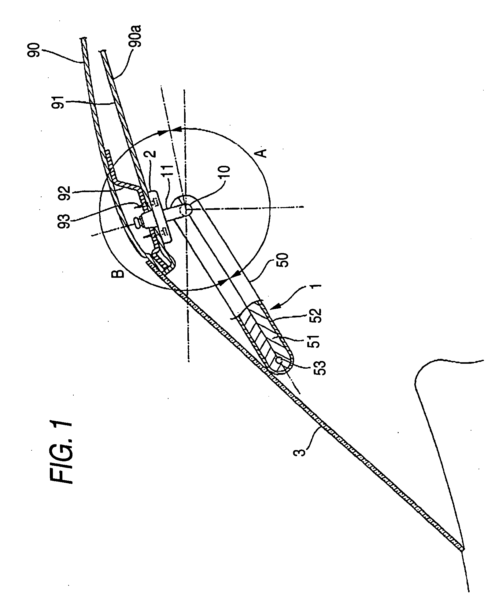
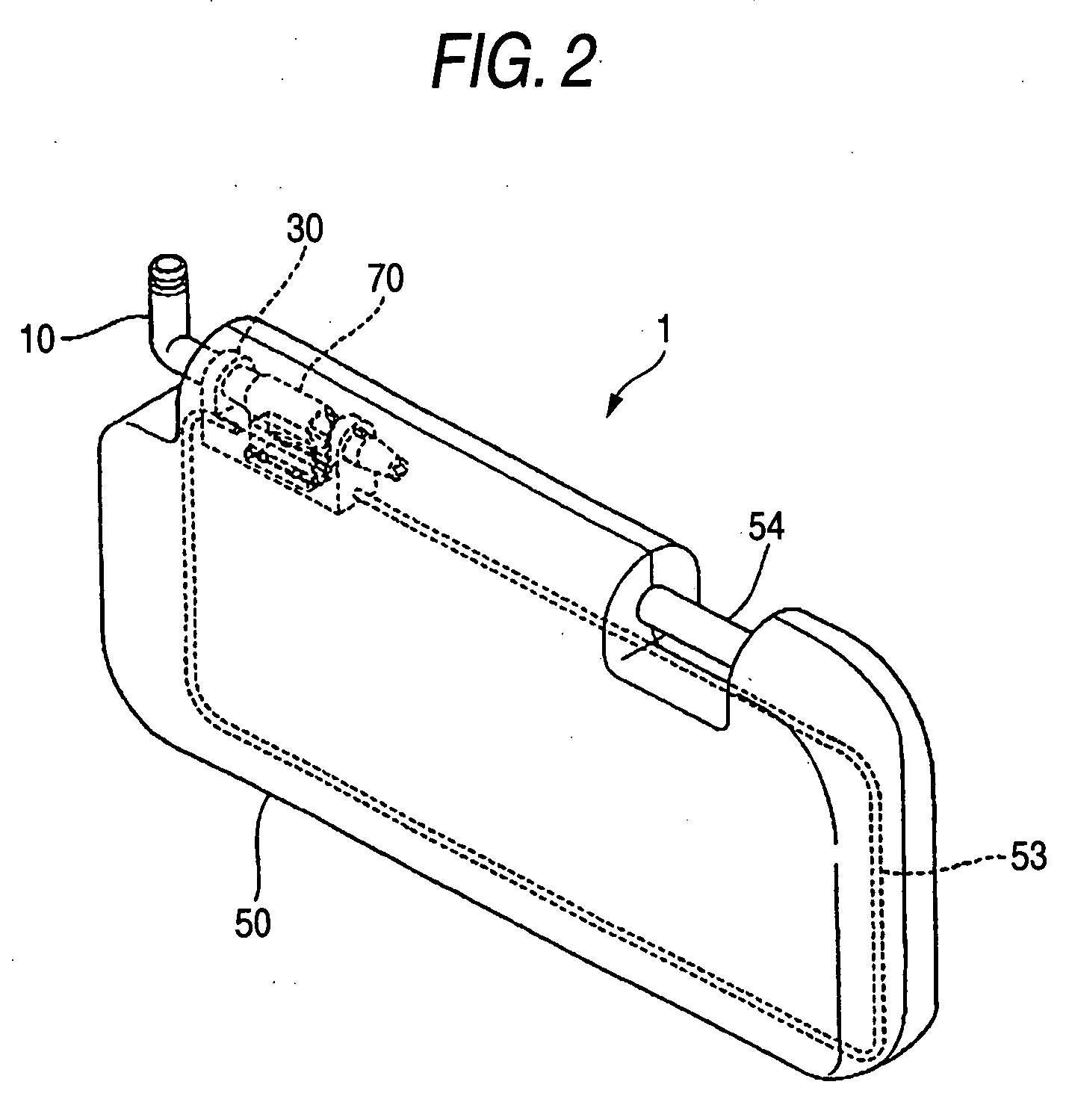
[0026] Preferred embodiments of a vehicular sun visor of the present invention will now be described with reference to FIGS. 1 to 9.

[0027] As shown in FIGS. 1 and 2, the sun visor 1 comprises a shaft 10 mounted on a vehicle body 90 through a bracket 2, a holder 30 rotatably supported on the shaft 10, a shielding plate (shielding member) 50 mounted on the holder 30, and a stabilizer 70 mounted on the holder 30 so as to hold a posture (angle) of the shielding plate 50. In this embodiment, the holder 30 and the stabilizer 70 jointly form a bearing member.

[0028] A shorter portion 11 of the shaft 10 is rotatably (or angularly movably) supported in the bracket 2, and this bracket 2 is mated with a roof panel interior member 91, and is fixed to a roof panel inner member 92 by screws 93. Namely, the shaft 10 is angularly movably mounted on a roof surface 90a within a passenger compartment of a vehicle through the bracket 2.

[0029] As shown in FIGS. 2 to 4, the shaft 10 has a generally L-s...


PUM


Abstract

A sun visor for a vehicle includes a shaft 10 angularly movably mounted on a roof surface within a passenger compartment of the vehicle, and a shielding plate angularly movably mounted on the shaft 10. A holder 30 and a stabilizer 70, in which the shaft 10 is angularly movably inserted, are provided at an end portion of the shielding plate, and a first projection 20A and a second projection 20B are formed on the shaft 10, and are spaced from each other in a direction of an axis of the shaft. The distance between the second projection 20B and the tubular portion 71 is larger than the distance between the first projection 20A and the bearing portion 33.

Description

BACKGROUND OF THE INVENTION [0001] This invention relates to a sun visor for a vehicle. [0002] Generally, a sun visor for a vehicle is mounted on a roof surface within a passenger compartment of the vehicle, and is disposed near to a front glass. The sun visor includes a shielding plate angularly movably supported on a shaft angularly movably mounted on a vehicle body. By angularly moving the shaft relative to the vehicle body, the shielding plate can be located along the front glass or a front door glass, and also by angularly moving the shielding plate relative to the shaft, the angle of use of the shielding plate can be changed. [0003] Incidentally, in a vehicle equipped with an airbag device, in some cases, a force, tending to withdraw or disengage the shielding plate from the shaft, acts on the sun visor upon deployment (or expansion) of an airbag. [0004] For example, when a shielding plate 101 of a sun visor 100 for a driver's seat is located along a front glass 110 as shown i...

Claims


Application Information

Patent Timeline
Patent Type & Authority Applications(United States)
IPC IPC(8): B60J3/00
CPCB60J3/0252B60J3/0265
Inventor IKEDA, KOJIHIROSE, TOSHIKAZUGOTO, TADAOHIRAYAMA, HIROYUKIWATANABE, TAKATOMOSOGA, JUNICHI
Owner HONDA MOTOR CO LTD
Learn More