
Filter system and method

Inactive Publication Date: 2006-08-03
BOSTON SCI SCIMED INC
View PDF99 Cites 104 Cited by
  • Summary
  • Abstract
  • Description
  • Claims
  • Application Information

AI Technical Summary

Problems solved by technology

Cardiac valves can become damaged and / or diseased for a variety of reasons.
Over time, the extra work can weaken the heart muscle.

Method used


Image

  • Filter system and method
  • Filter system and method
  • Filter system and method

Examples


Embodiment Construction

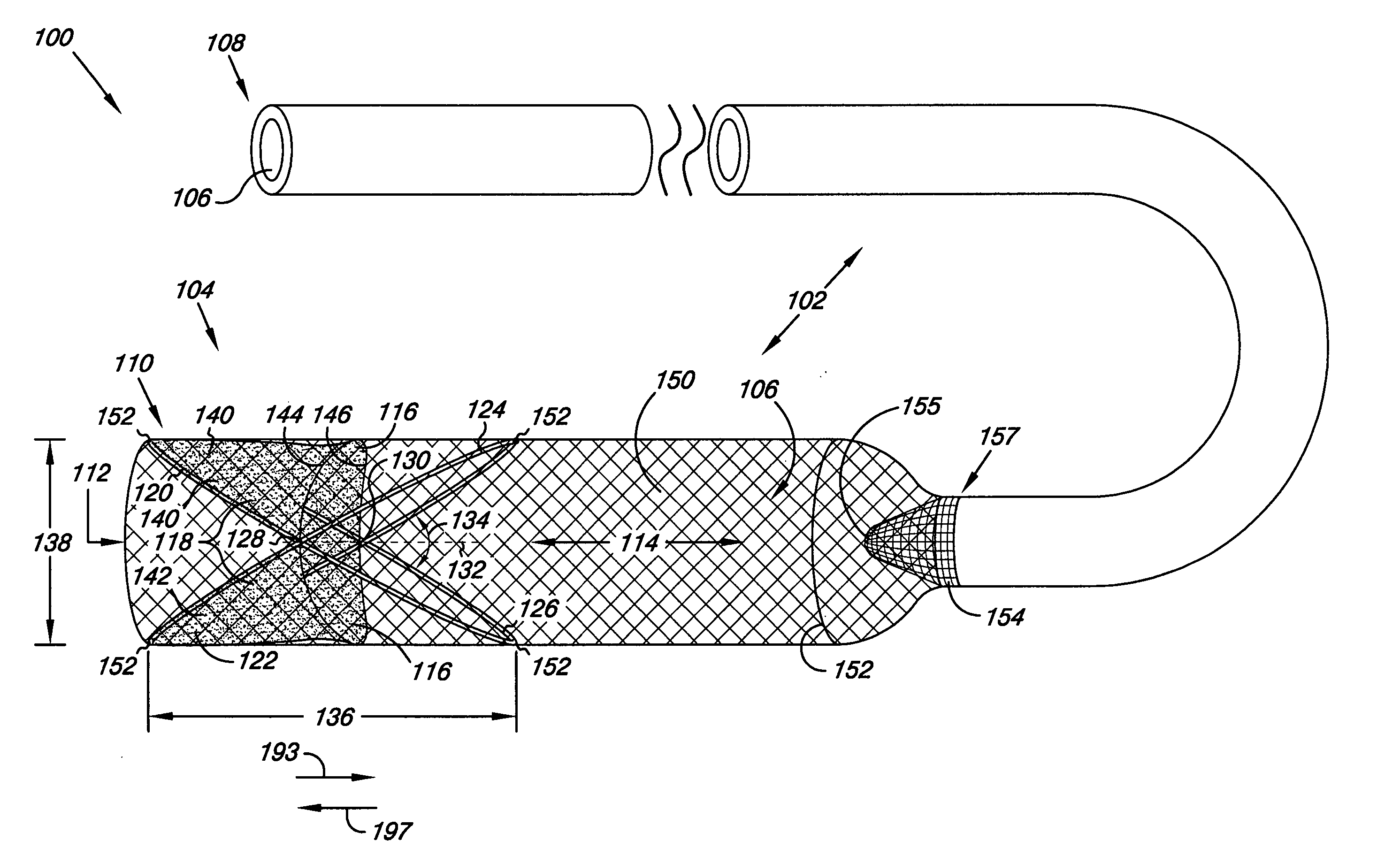
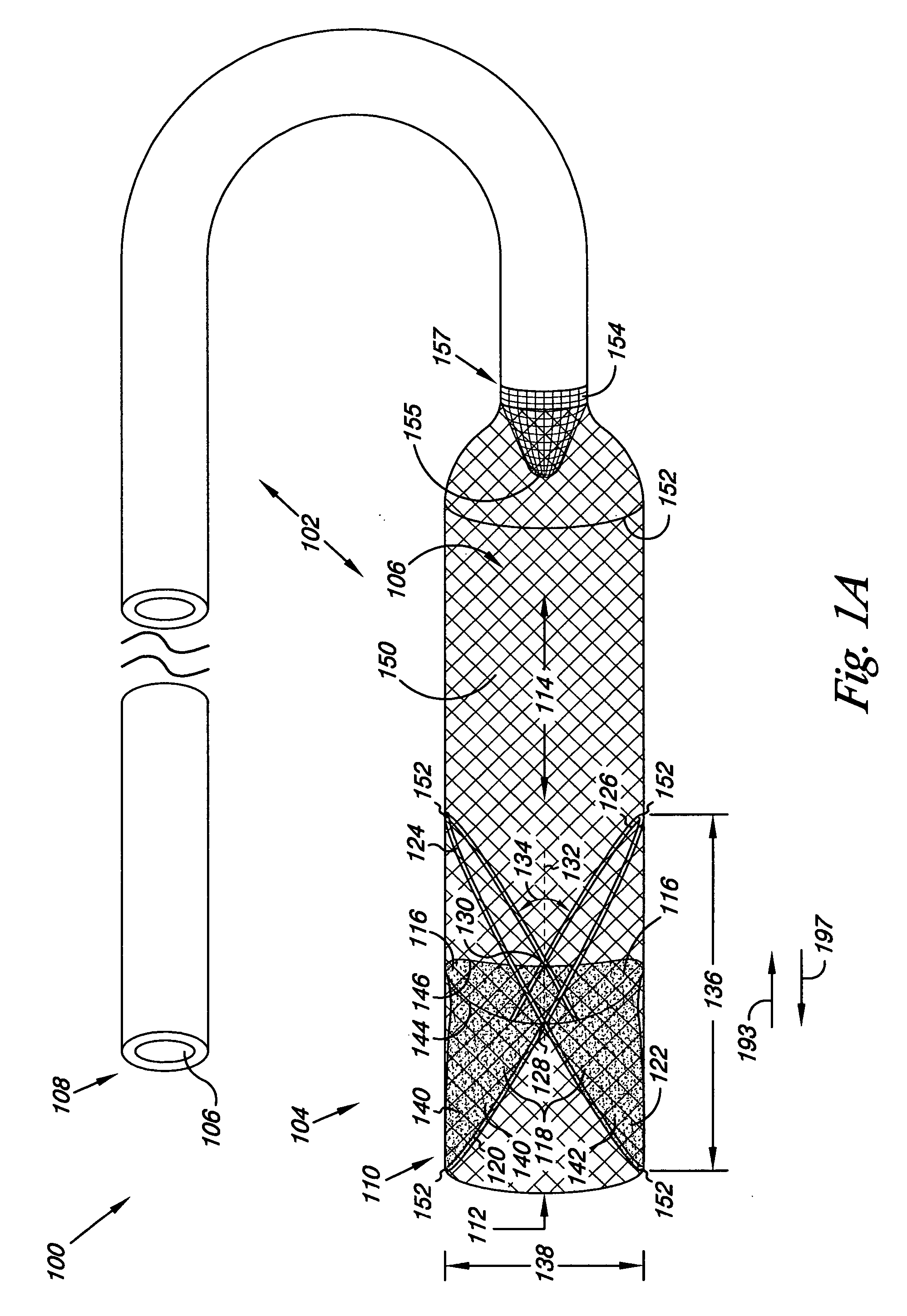
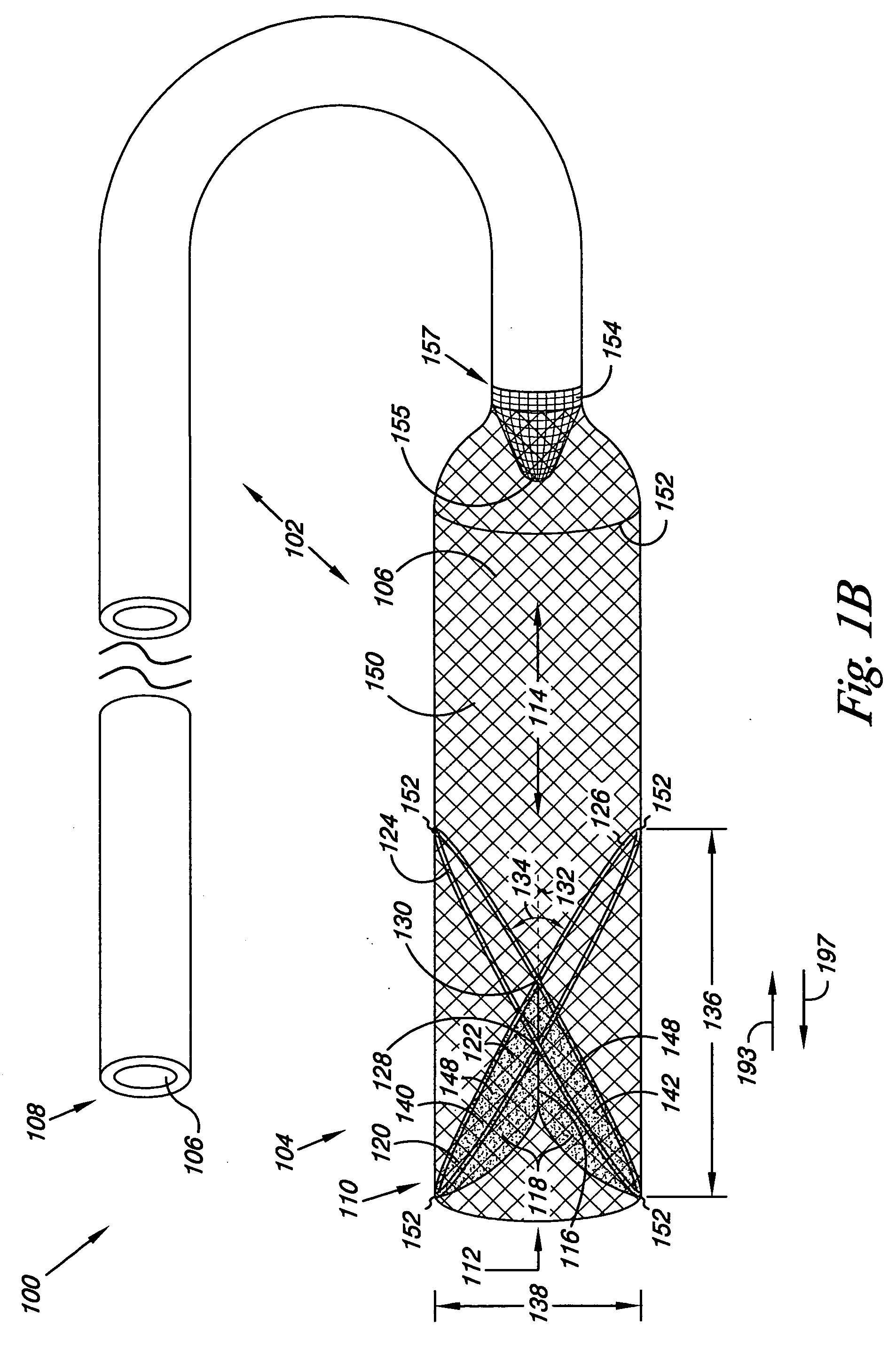
[0010] Embodiments of the present invention are directed to a filter system and method for temporary placement and use in a lumen. Embodiments of the present invention are also directed to augmenting cardiac valve function while filtering fluid moving within the lumen. For example, the filter system and method can be used to temporarily replace, or augment, an incompetent valve in a body lumen and / or can be used as a temporary valve during a procedure to repair or to replace an incompetent valve with a prosthetic valve.

[0011] Embodiments of the filter system can further include a sheath that can be used to help position the filter system within a body lumen, such as an artery or a vein, through minimally-invasive techniques. In further embodiments, additional structures can be used in conjunction with the filter system. For example, catheters having tissue shearing capability, stent delivery capability, and prosthetic valve delivery capability can also be used in conjunction with t...


PUM


Abstract

A filter system, comprising an elongate filter body defining a lumen and having a proximal end and a distal end. A valve can be provided defining a lumen and having a reversibly sealable opening for unidirectional flow of a fluid through the lumen. The valve can be adjoined proximal the distal end of the elongate filter body, wherein the elongate filter body filters the unidirectional flow of the fluid passing through the lumen of the valve and the lumen of the elongate filter body.

Description

FIELD OF THE INVENTION [0001] The present invention relates generally to apparatus, systems, and methods for use in a lumen; and more particularly to a valve and filter apparatus, system, and method for use in the vasculature system. BACKGROUND OF THE INVENTION [0002] Cardiac valves can become damaged and / or diseased for a variety of reasons. Damaged and / or diseased cardiac valves are grouped according to which valve or valves are involved, and the amount of blood flow that is disrupted by the damaged and / or diseased valve. The most common cardiac valve diseases occur in the mitral and aortic valves. Diseases of the tricuspid and pulmonary valves are fairly rare. [0003] The aortic valve regulates the blood flow from the heart's left ventricle into the aorta. The aorta is the main artery that supplies oxygenated blood to the body. As a result, diseases of the aortic valve can have a significant impact on an individual's health. Examples of such diseases include aortic regurgitation a...

Claims


Application Information

Patent Timeline
IPC IPC(8): A61M29/00A61M25/10
CPCA61F2/013A61F2/2418A61F2/2433A61F2/958A61F2002/011A61F2220/0066A61F2230/008A61F2002/018A61F2230/0006A61F2220/005A61F2230/0069A61F2210/0019A61F2/011A61F2002/016
Inventor LAFONTAINE, DANIEL M.JENSON, MARK L.DRASLER, WILLIAM J.
Owner BOSTON SCI SCIMED INC
Learn More