
Secure surface mounted dispensing system

a dispenser and surface mount technology, applied in the direction of liquid transfer devices, couplings, rod connections, etc., can solve the problems of considerable time and logistics, and achieve the effect of convenient flush mounting of the flat back

Active Publication Date: 2006-07-27
PACIFIC WORLD
View PDF16 Cites 14 Cited by
  • Summary
  • Abstract
  • Description
  • Claims
  • Application Information

AI Technical Summary

Benefits of technology

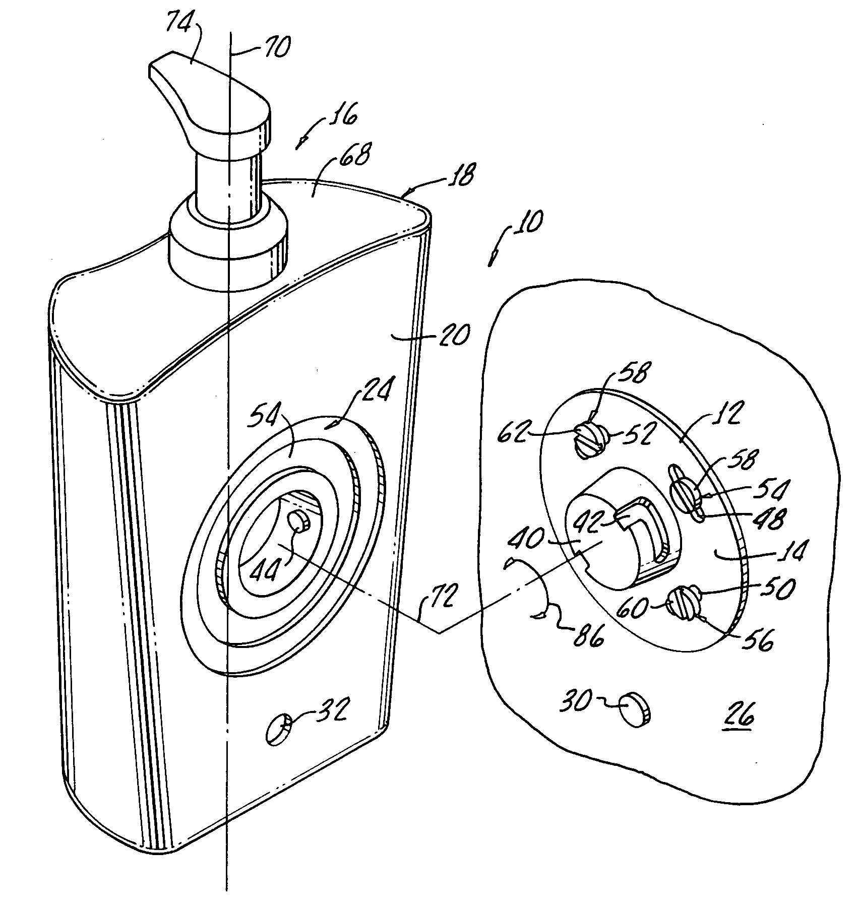
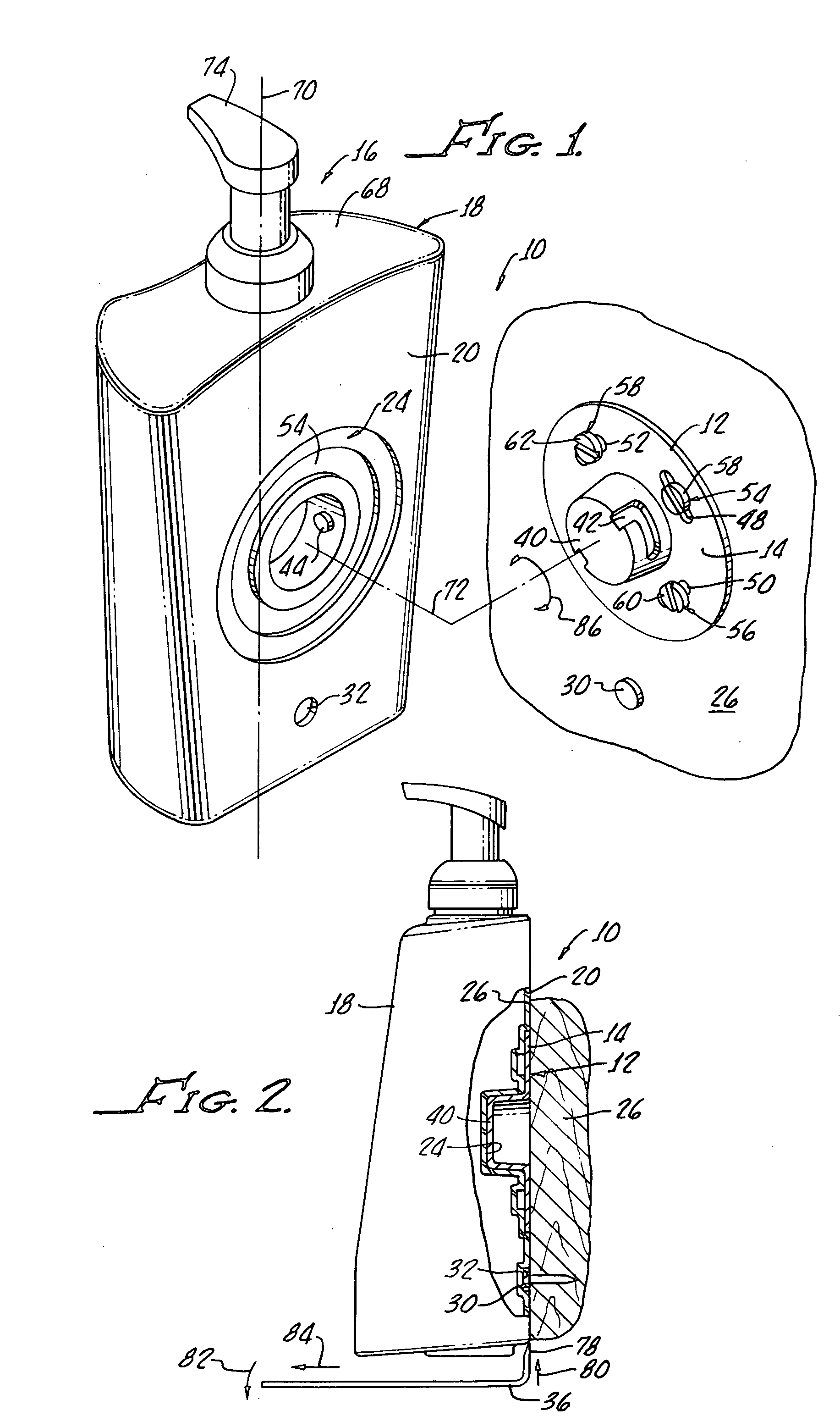
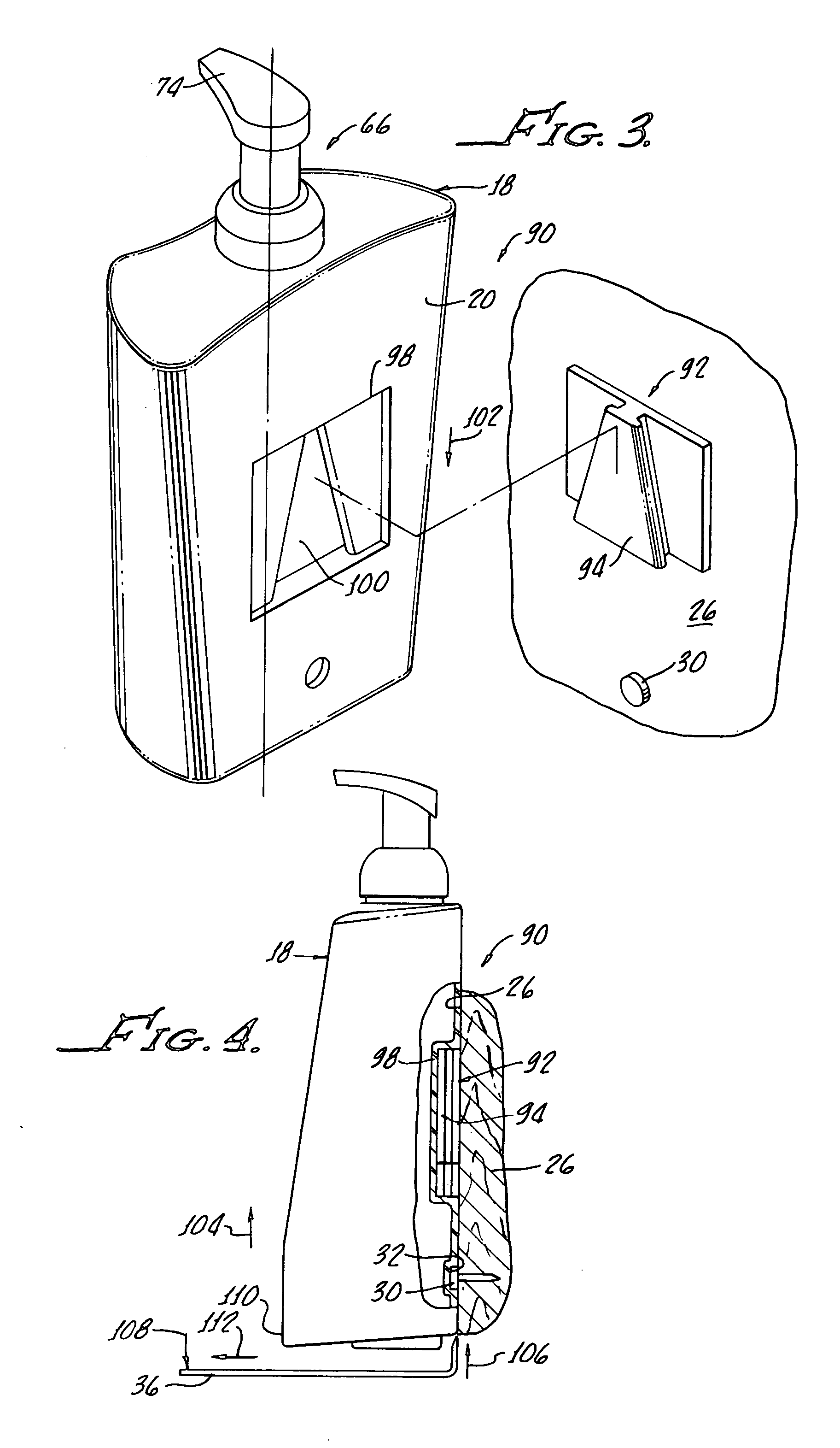
The present invention is a bracket for securing a bottle to a surface. The bracket includes a mounting flange with openings for receiving threaded screws to fix the bracket to a surface. The bracket also has an embossment with a circular groove for receiving the screw heads to enable flush mounting of the flat back of the bottle and secure it to the bracket. The bracket also includes a release tool that can be inserted between the bottle and the surface to separate the button from the bracket and remove the bottle from the bracket. This prevents unauthorized removal of the bottle from the bracket and surface.

Problems solved by technology

The technical problem of this patent text is to provide a more efficient and cost-effective method for producing a specific type of chemical compound.

Method used


Image

  • Secure surface mounted dispensing system
  • Secure surface mounted dispensing system
  • Secure surface mounted dispensing system

Examples


Embodiment Construction

[0021] With reference to FIGS. 1 and 2, there is shown flush mount dispensing bottle and bracket apparatus 10 generally including a bracket 12 having a mounting flange 14 and a bottle 18 having a flat back 20 which includes an embossment 24 for receiving the flange 14 and enabling the flat back to flushly engage a surface 26 supporting the bracket 12, as more clearly shown in FIG. 2.

[0022] A button 30 attachable to the surface 26 by any conventional manner is disposed at a spaced apart distance from the bracket 12 and a second embossment 32 is provided in the flat back 20 for receiving a button 30 and further facilitating flush contact between the flat back 20 and the surface 26, as illustrated in FIG. 2. The button functions to prevent, or inhibit, unauthorized removal of the bottle 18 from the bracket 12.

[0023] Preferably, the bottle 18 is molded from plastic and any bracket 12 may be either plastic or metal. A suitable plastic provides resiliency for enabling the bottle 18 to b...


PUM


Abstract

Flush mount dispensing bottle and apparatus includes a bracket having a mounting flange and a bottle having a flat back with an embossment for receiving the flange and enabling the flat back to flushly contact a surface supporting the bracket. A button attachable to the surface at a spaced apart distance from the bracket is provided and a second embossment receiving the button enables the flat back to flushly contact the surface and further prevents unauthorized removal of the bottle from the bracket.

Description


Claims


Application Information

Patent Timeline
Owner PACIFIC WORLD
Learn More