
Semiconductor light emitting device mounting substrates including a conductive lead extending therein and methods of packaging same

Active Publication Date: 2006-07-20
CREELED INC
View PDF35 Cites 83 Cited by
  • Summary
  • Abstract
  • Description
  • Claims
  • Application Information

AI Technical Summary

Problems solved by technology

As a result, the thermal impedance for such packages may be higher and a thermal mismatch may result among the various components within a package that may cause reliability problems with a package.
For example, problems may result at an interface between a copper metal of a heat sink or cavity with a plastic of a body in which such a heat sink or cavity is mounted.
In addition, assembly may be more complicated because of increased piece part counts for the package.
In addition, where a sheet metal optical cavity is utilized, a cavity typically can only be fabricated in a limited range of depth and shape configurations.
A larger optical cavity space may also result in such multipart packages, resulting in greater volumes of encapsulant in use, which may increase problems related to delamination and formation of bubbles within the encapsulant during temperature cycles.
Such a product may not be surface mount technology (SMT) compatible as its packaging materials generally cannot withstand solder reflow temperatures.
In addition, during use, the soft encapsulant may tend to form bubbles or delaminate from the enclosure walls, which may adversely affect device reliability.

Method used


Image

  • Semiconductor light emitting device mounting substrates including a conductive lead extending therein and methods of packaging same
  • Semiconductor light emitting device mounting substrates including a conductive lead extending therein and methods of packaging same
  • Semiconductor light emitting device mounting substrates including a conductive lead extending therein and methods of packaging same

Examples


Embodiment Construction

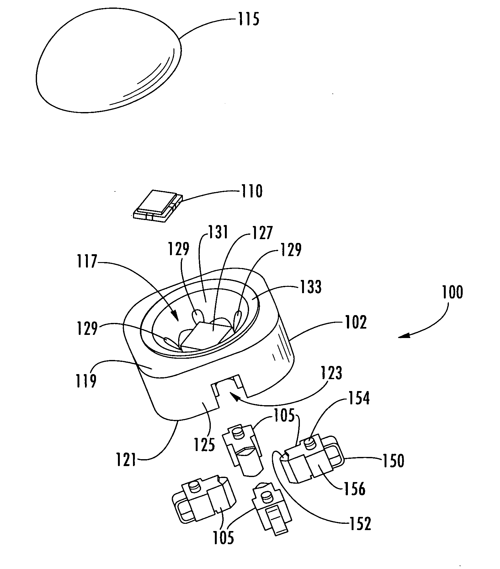
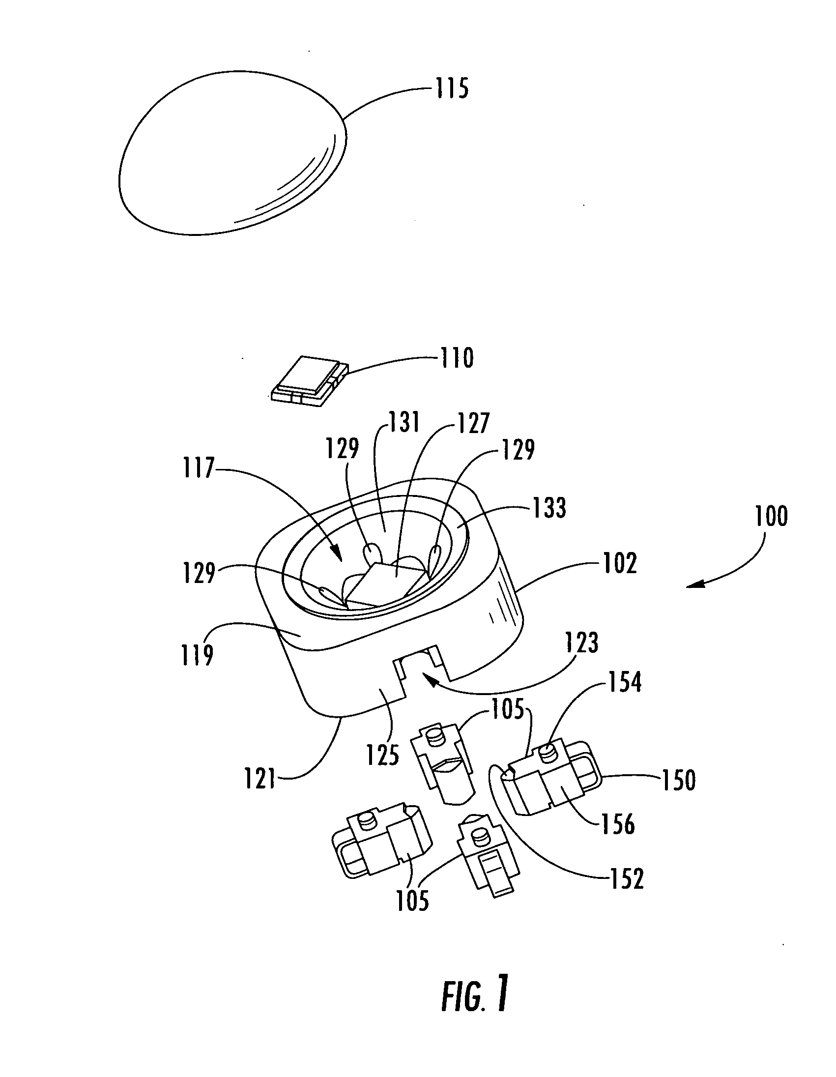
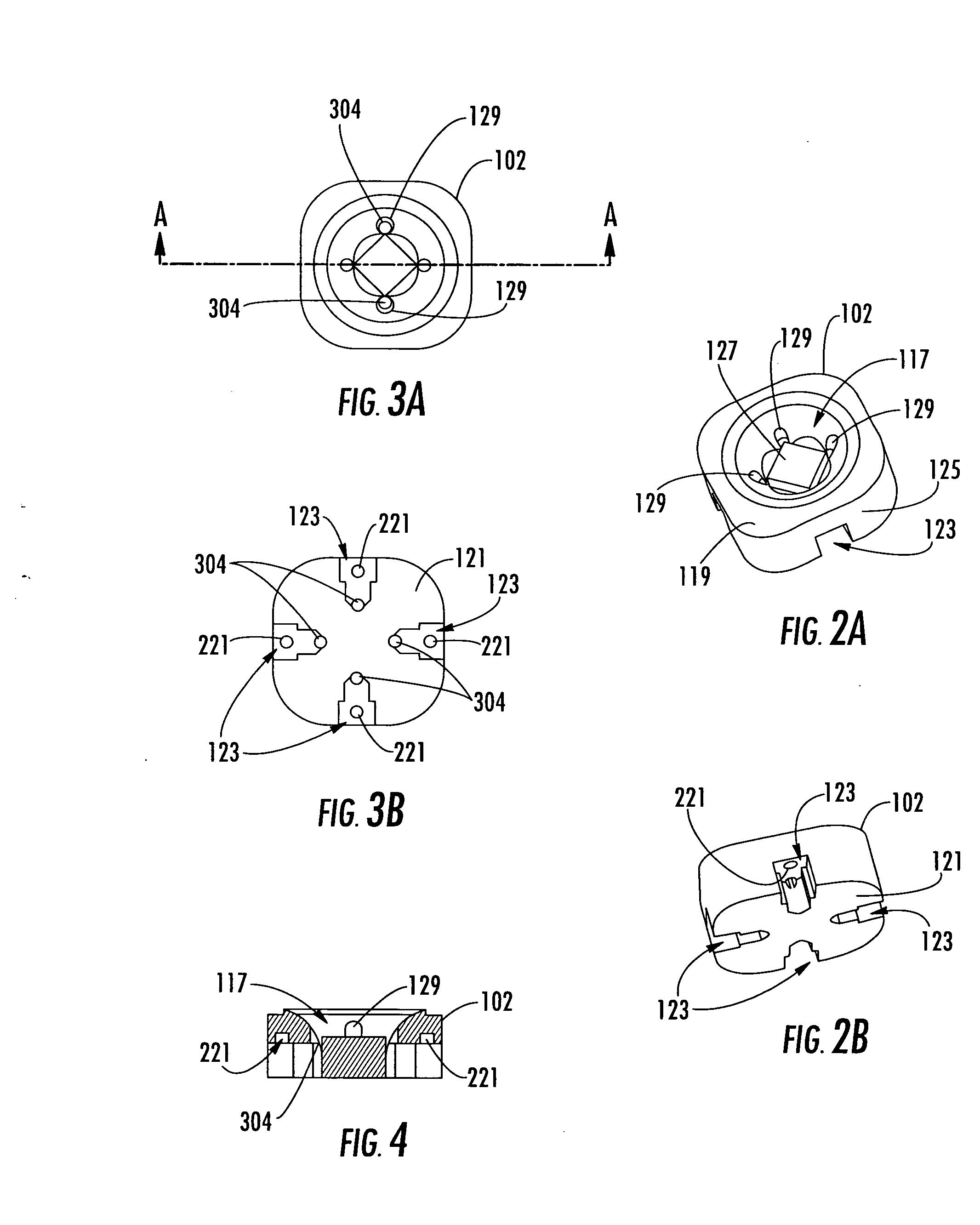
[0036] The present invention now will be described more fully hereinafter with reference to the accompanying drawings, in which embodiments of the invention are shown. However, this invention should not be construed as limited to the embodiments set forth herein. Rather, these embodiments are provided so that this disclosure will be thorough and complete, and will fully convey the scope of the invention to those skilled in the art. In the drawings, the thickness of layers and regions are exaggerated for clarity. Like numbers refer to like elements throughout. As used herein the term “and / or” includes any and all combinations of one or more of the associated listed items and may be abbreviated as “ / ”.

[0037] The terminology used herein is for the purpose of describing particular embodiments only and is not intended to be limiting of the invention. As used herein, the singular forms “a”, “an” and “the” are intended to include the plural forms as well, unless the context clearly indica...


PUM


Abstract

A mounting substrate for a semiconductor light emitting device includes a thermally conductive mounting block. The mounting block has, in a first face thereof, a cavity that is configured to mount a semiconductor light emitting device therein and to reflect light that is emitted by the semiconductor light emitting device that is mounted therein away from the cavity. A conductive lead inserted into the mounting block extends into the cavity. The conductive lead is electrically isolated from the mounting block and has an exposed contact portion in the cavity. The conductive lead may be a plurality of conductive leads each having an exposed contact portion at different locations in the cavity. Related packaging methods also may be provided.

Description

FIELD OF THE INVENTION [0001] This invention relates to semiconductor light emitting devices and manufacturing methods therefor, and more particularly to packaging and packaging methods for semiconductor light emitting devices. BACKGROUND OF THE INVENTION [0002] Semiconductor light emitting devices, such as Light Emitting Diodes (LEDs) or laser diodes, are widely used for many applications. As is well known to those having skill in the art, a semiconductor light emitting device includes one or more semiconductor layers that are configured to emit coherent and / or incoherent light upon energization thereof. It is also known that the semiconductor light emitting device generally is packaged to provide external electrical connections, heat sinking, lenses or waveguides, environmental protection and / or other functions. [0003] For example, it is known to provide a two-piece package for a semiconductor light emitting device, wherein the semiconductor light emitting device is mounted on a s...

Claims


Application Information

Patent Timeline
IPC IPC(8): H01L33/00H01L33/48H01L33/60H01L33/62
CPCH01L25/0753H01L33/486H01L33/60H01L33/62H01L2224/48091H01L2924/00014H01L2924/01019H01L2924/01068H01L2924/12041H01L2924/3011H01L2924/00
Inventor LOH, BAN P.NEGLEY, GERALD H.FU, YANKUN
Owner CREELED INC
Learn More