
Data migration with reduced contention and increased speed

a data migration and speed technology, applied in the field of data migration efficiency, can solve the problems of slow data migration and/or customer workload, high speed variety, and high cost of additional high-speed storage devices such as dasd (direct access storage devices), and achieve the effect of reducing avoiding contention between migration and space allocation

Inactive Publication Date: 2006-07-13
IBM CORP
View PDF5 Cites 42 Cited by
  • Summary
  • Abstract
  • Description
  • Claims
  • Application Information

AI Technical Summary

Benefits of technology

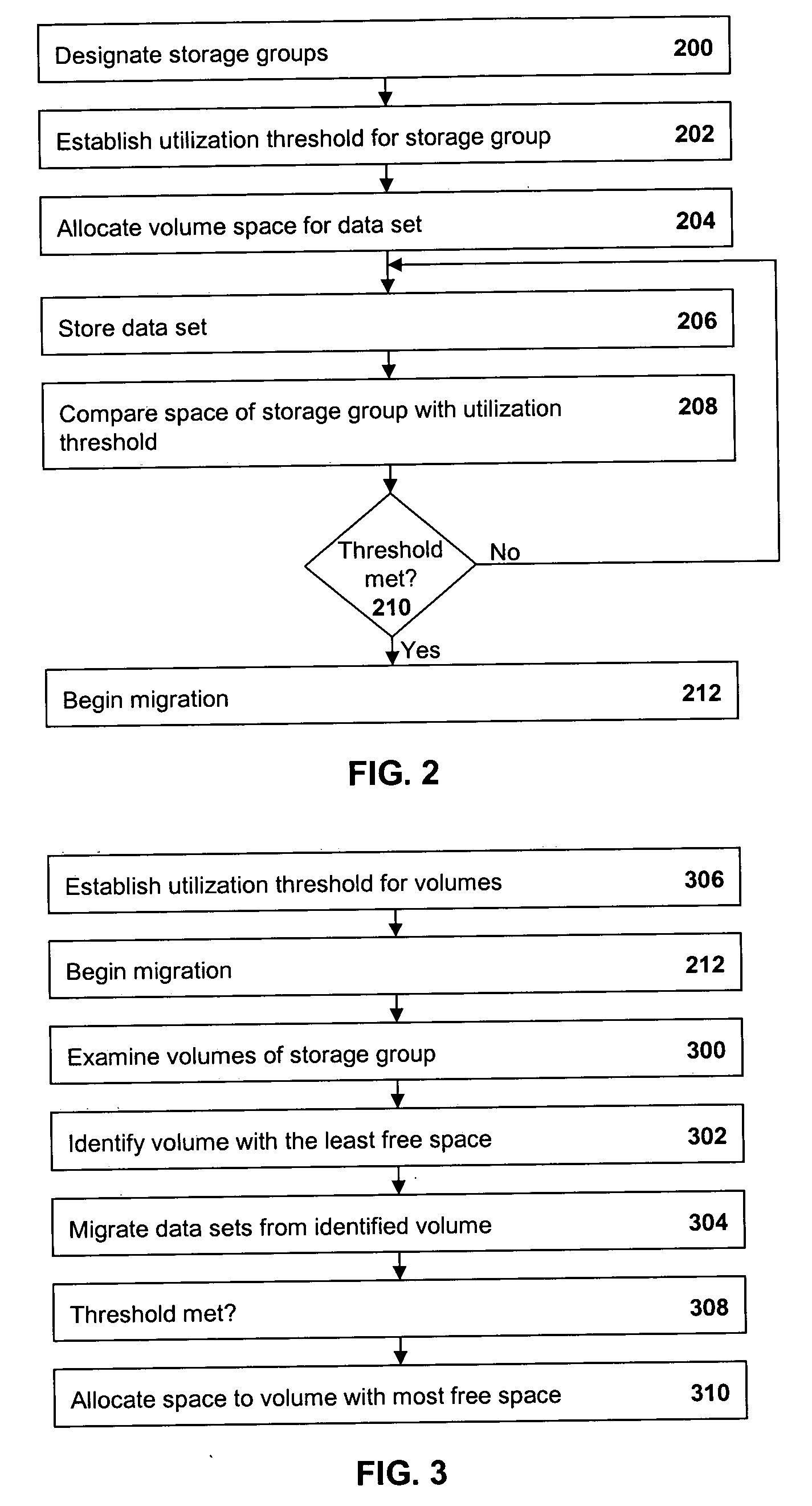
[0008] In one embodiment, high threshold are assigned to each storage group and, when the space used in a storage group reaches or exceeds the high threshold, migration of data will begin from volumes in the storage group, beginning with the volume having the least free space. Thus, contention between migration and space allocation is reduced.
[0009] In another embodiment, when a volume is selected for migration, a flag is set which prevents space in the volume from being allocated to new data sets. Upon completion of the migration, the flag is cleared and allocation is allowed. Thus, contention between migration and space allocation is avoided.

Problems solved by technology

However, installing additional high speed storage devices, such as DASD (direct access storage device), can become expensive.
Moreover, not all of a customer's storage may need to be of the expensive, high speed variety.
Such a conflict causes contention for common resources, including volume table of contents (VTOCs), catalog entries and the like, resulting in a slowdown in data migration and / or customer workload.

Method used


Image

  • Data migration with reduced contention and increased speed
  • Data migration with reduced contention and increased speed
  • Data migration with reduced contention and increased speed

Examples


Embodiment Construction

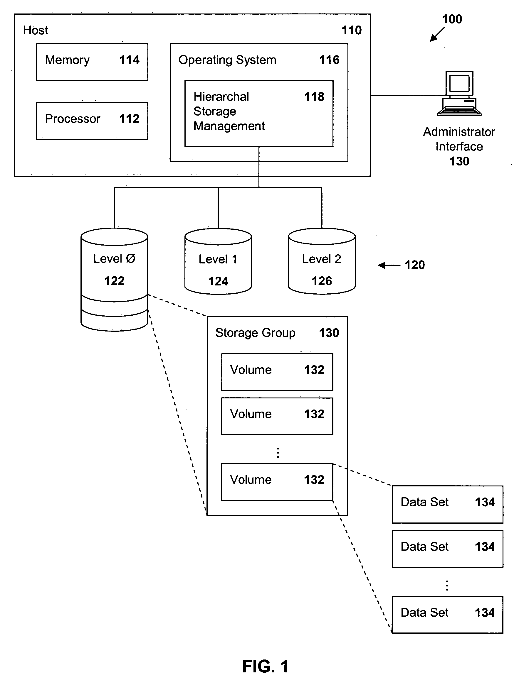
[0013]FIG. 1 is a block diagram of a hierarchal storage system 100 in which the present invention may be incorporated. The system 100 includes a host device 110 to which is attached multiple levels of data storage devices 120 and an administrative interface, 130. The host 110 includes a processor 112, memory 114 and an operating system 116. The operating system 116 includes hierarchal storage management functions 118. For purposes of this description, the hierarchal storage manager 118 is illustrated as being operatively coupled to the storage devices 120. However, other processes in the operating system 116 and / or the host 110 may access the storage devices 120. Thus, as used herein, the term “coupled” may refer to an indirect relationship of two components, devices or subsystems as well as to a direct electrical connection between the two.

[0014] The storage devices 120 include high speed (and expensive) Level 0 storage 122, and slower (and less expensive) Level 1 storage 124. Add...


PUM


Abstract

Methods and apparatus are provided for managing data in a hierarchal storage subsystem. A plurality of volumes is designated as a storage group for Level 0 storage; a high threshold is established for the storage group; space is allocated for a data set to a volume of the storage group, storing the data set to the volume; the high threshold is compared with a total amount of space consumed by all data sets stored to volumes in the storage group; and data sets are migrated from the storage group to a Level 1 storage if the high threshold is less than or equal to the total amount of space used by all of the data sets stored to volumes in the storage group. Optionally, high threshold are assigned to each storage group and, when the space used in a storage group reaches or exceeds the high threshold, migration of data will begin from volumes in the storage group, beginning with the volume having the least free space. Thus, contention between migration and space allocation is reduced. Also optionally, when a volume is selected for migration, a flag is set which prevents space in the volume from being allocated to new data sets. Upon completion of the migration, the flag is cleared and allocation is allowed. Thus, contention between migration and space allocation is avoided.

Description

TECHNICAL FIELD [0001] The present invention relates to the efficient migration of data between storage levels in a hierarchal storage subsystem. BACKGROUND ART [0002] A data processing facility typically includes one or more host devices to which are attached storage devices, either directly or through a network. As a customer's business grows, the need for increased storage also grows. However, installing additional high speed storage devices, such as DASD (direct access storage device), can become expensive. Moreover, not all of a customer's storage may need to be of the expensive, high speed variety. Rather, such storage may be allocated to data which is to be accessed frequently while less frequently accessed data may be stored on slower and less expensive storage devices, such as tape cartridges. Storage with multiple levels is said to be configured as hierarchal storage. [0003] The operating system of the host may include a hierarchal storage manager. The OS / 390® or z / OS® ope...

Claims


Application Information

Patent Timeline
Patent Type & Authority Applications(United States)
IPC IPC(8): G06F12/00
CPCG06F3/0619G06F3/0647G06F3/0685G06F12/023
Inventor SMITH, MAX D.
Owner IBM CORP
Learn More