
Orthopedic system for total hip replacement surgery

Inactive Publication Date: 2006-07-13
ORTHOPAEDIC DEV
View PDF15 Cites 5 Cited by
  • Summary
  • Abstract
  • Description
  • Claims
  • Application Information

AI Technical Summary

Benefits of technology

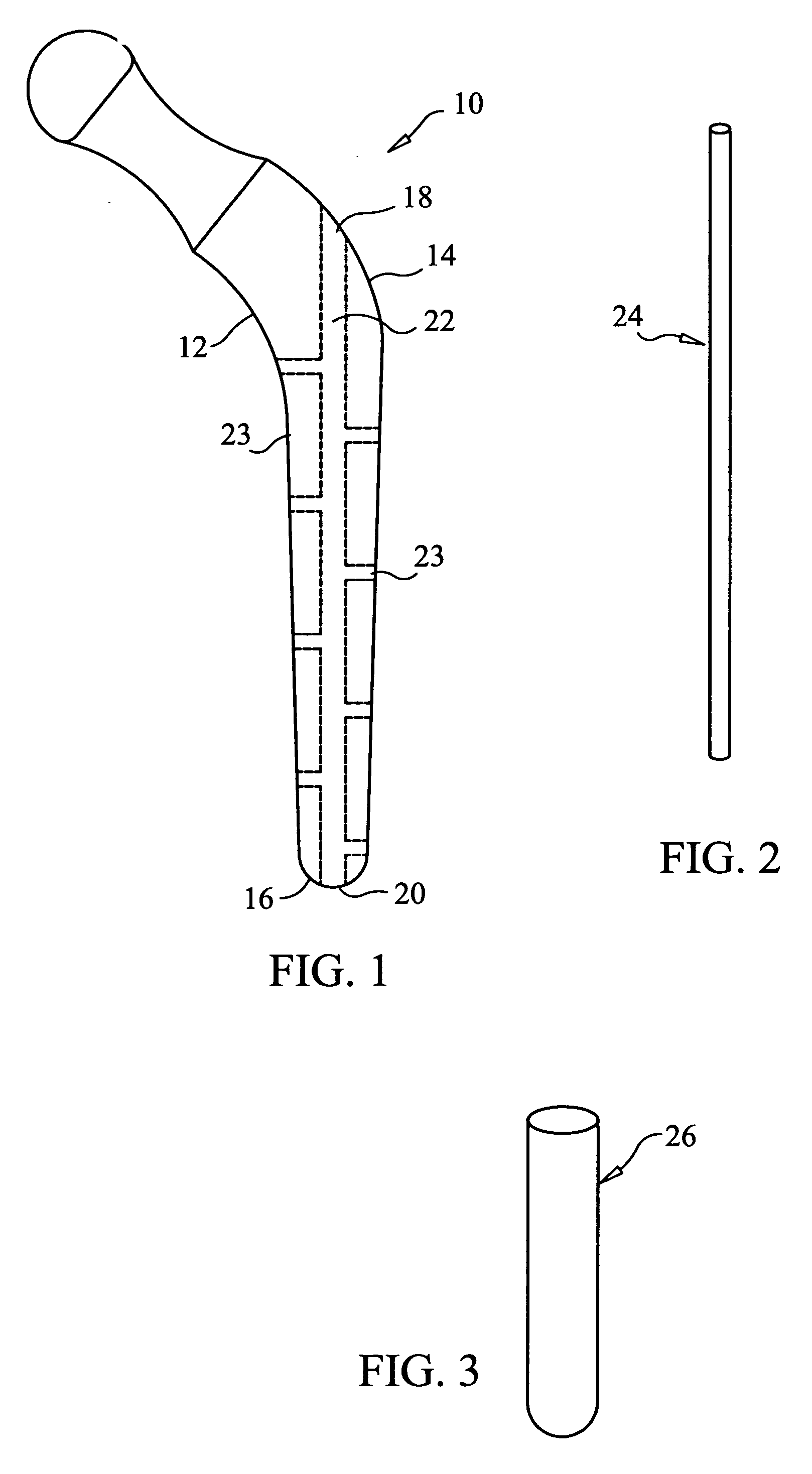
[0008] The present invention provides an orthopedic prosthesis which can be properly aligned within a prepared cavity of bone segment, while minimizing the surgically invasive opening in a patient. An exemplary embodiment of the present invention includes an implantable orthopedic prosthesis having an elongate body defining a proximal and a distal end. The implantable orthopedic prosthesis further includes a first opening, a second opening, and a bore extending from the first opening to the second opening. At least one seepage port extends from an exterior surface of the prosthesis to the bore. Moreover, a guide wire is included that is adapted to fit within the bore of the orthopedic prosthesis. Finally, the present invention also includes a resorbable insert containing substrates that promote bone growth, are anti-bacterial, or are anti-inflammatory, where the insert is adapted to fit within the bore of the orthopedic prosthesis.
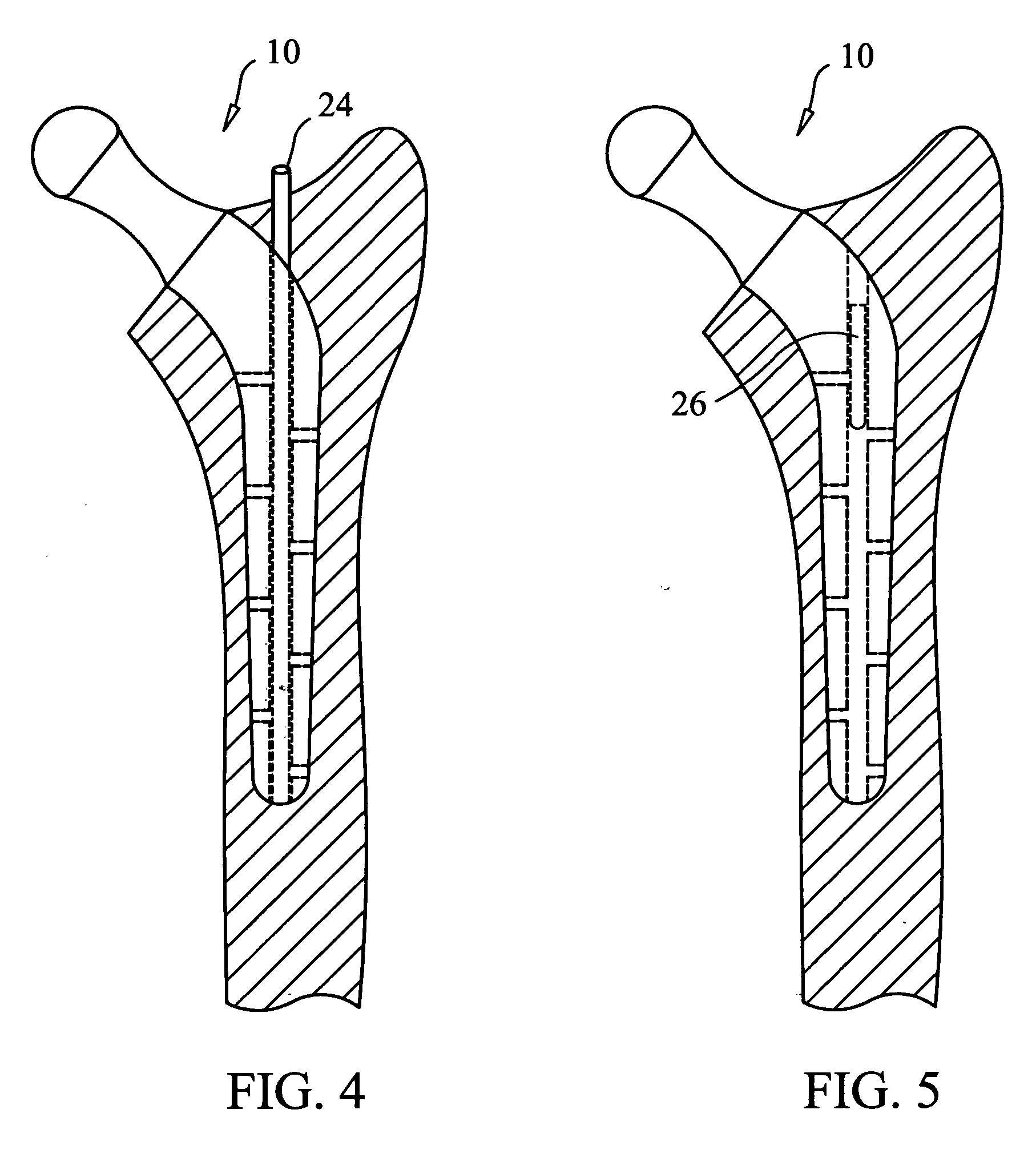
[0009] The present invention further provides a method for implanting an orthopedic device, wherein the guide wire is inserted into an intramedullary canal of a prepared bone. Once the guide wire is positioned, the orthopedic prosthesis is moved along the guide wire, where a portion of the guide wire is located in the bore of the prosthesis. The guide wire is then used to align and steer the prosthesis into the proper position in the prepared bone cavity without the need for image guidance equipment or requiring a large incision. Upon alignment and insertion of the prosthesis, the guide wire is removed, and the resorbable insert is placed in the bore of the orthopedic prosthesis in order to promote healing.

Problems solved by technology

If a prosthesis is misaligned with the femur upon implantation, the misalignment can result in excessive wear of the prosthesis, as well as loosening of the prosthesis within the femoral cavity, and may result in increased pain experienced by the patient.
However, while a larger incision may provide more room for a surgeon to manipulate the prosthetic implant into proper alignment, it will also result in a larger area of tissue which has to subsequently heal, thereby increasing the size of any scar resulting from the surgical procedure.
Unfortunately, minimizing the surgical opening reduces the ability of the surgeon to properly position an orthopedic implant.
Moreover, lengthy procedures and the use of image guidance equipment are often required to accomplish proper alignment.

Method used


Image

  • Orthopedic system for total hip replacement surgery
  • Orthopedic system for total hip replacement surgery
  • Orthopedic system for total hip replacement surgery

Examples


Embodiment Construction

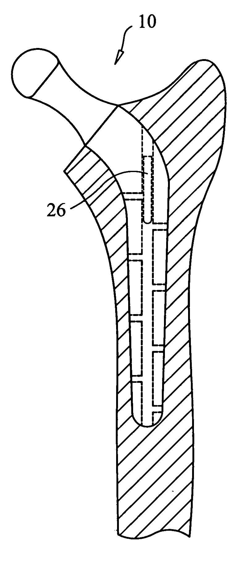
[0016] In an exemplary embodiment, the present invention provides an orthopedic system including an orthopedic prosthesis 10 adaptable for implantation into a prepared cavity of a bone, as shown in FIG. 1. The orthopedic prosthesis 10 includes an elongate body 12 defining a proximal end 14 and a distal end 16, and includes a femoral stem prosthesis 12 implanted during a hip arthroplasty procedure. The femoral stem 12 further defines a first opening 18, a second opening 20, and a bore 22 extending from the first opening 18 to the second opening 20. The first opening 18 and the second opening 20 may be located at or substantially near the proximal end 14 and the distal end 16, respectively. However, the location of the first and second openings may be modified in order to facilitate a desired orientation of the prosthesis 10 in a prepared bone cavity upon implantation. By modifying the location of the openings, the alignment of the bore 22 is inherently modified, and may result in the...


PUM

PropertyMeasurementUnit
Lengthaaaaaaaaaa
Lengthaaaaaaaaaa
Lengthaaaaaaaaaa

Abstract

An orthopedic system including an orthopedic prosthesis having an exterior surface, the prosthesis defining a proximal end and a distal end, a first opening located substantially near the proximal end, a second opening located substantially near the distal end, and a bore extending from the first opening to the second opening. The orthopedic prosthesis also includes a seepage port extending from the exterior surface of the prosthesis and providing a passage to the bore, as well as a guidewire, wherein at least a portion of the guidewire is positionable within the bore, and a resorbable insert positionable within the bore.

Description

BACKGROUND OF THE INVENTION [0001] 1. Statement of the Technical Field [0002] The present invention relates to an orthopedic prosthesis, particularly a system and method for aligning an orthopedic prosthesis. [0003] 2. Description of the Related Art [0004] As natural joints in the human body deteriorate due to injury, disease or aging, artificial joint prostheses can be implanted to improve the comfort and quality of life of an individual. Among the more common joint prostheses known are those involved in the replacement of the hip joint. When performing a hip arthroplasty, a cavity is generally created in a proximal portion of a patient's femur which will eventually receive the femoral stem of an implanted prosthesis. Similar replacement techniques for joints other than the hip also include the formation of comparable cavities within existing bone which will eventually house a prosthesis component. [0005] Upon the creation of such a cavity, the prosthesis can be secured using numer...

Claims


Application Information

Patent Timeline
IPC IPC(8): A61F2/36A61F2/46
CPCA61F2/30744A61F2/36A61F2/3662A61F2002/2817A61F2002/30062A61F2002/30113A61F2002/30153A61F2002/30224A61F2002/30677A61F2002/30726A61F2002/30733A61F2002/30787A61F2002/30789A61F2002/368A61F2002/3684A61F2002/3694A61F2002/4677A61F2210/0004A61F2230/0006A61F2230/0019A61F2230/0069A61F2310/00017A61F2310/00023
Inventor KATZMAN, SCOTT STEVEN
Owner ORTHOPAEDIC DEV
Learn More