
Shell for electrical connector

a technology of electrical connectors and shells, applied in the direction of coupling device connections, coupling protective earth/shielding arrangements, electrical apparatus, etc., can solve the problems of component displacement, excessive inserting of connectors, and inability to guarantee the prior fastening, so as to prevent the housing from slipping

Inactive Publication Date: 2006-07-13
ADVANCED CONNECTEK INC
View PDF3 Cites 29 Cited by
  • Summary
  • Abstract
  • Description
  • Claims
  • Application Information

AI Technical Summary

Benefits of technology

[0008] It is therefore an object of the present invention to provide an electrical connector shell having stop members with a housing and terminals enclosed so as to form the electrical connector. By utilizing the electrical connector shell, it is possible of preventing the housing from displacing due to an excessive insertion force exerted by the mating connector.

Problems solved by technology

But the prior fastening is not reliable.
It is possible of inserting the connector excessively to push a housing of the connector backward if sufficient care is not taken.
Also, problems such as component displacement, poor electrical contact, and insufficient fastening force between the housing and the shell of the mating connector occur.
To the worse, a peripheral device mounted with the connector may fall on the ground if sufficient care is not taken in plugging or unplugging the connector.

Method used


Image

  • Shell for electrical connector
  • Shell for electrical connector
  • Shell for electrical connector

Examples


Embodiment Construction

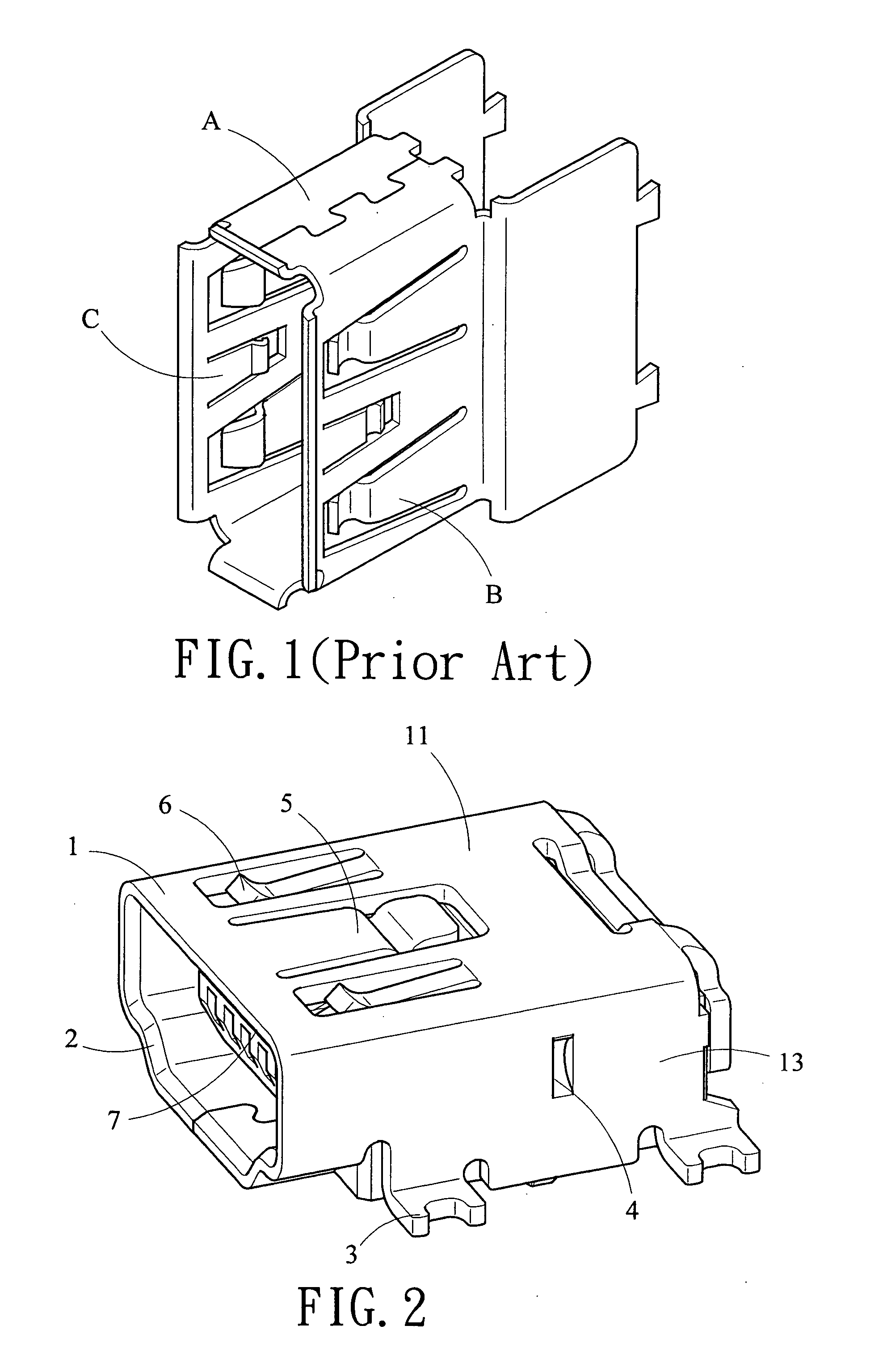
[0017] Referring to FIG. 2, which is a perspective view of a first preferred embodiment of electrical connector according to the invention. A shell 1 encloses a terminal seat 7 formed by a housing and terminals. An electrical connector is comprised of the shell 1 and the terminal seat 7. The electrical connector comprises a mating port 2 for permitting a mating connector to connect thereto for electrical connection. In the first embodiment, the electrical connector is adapted to mounted on a printed circuit board (PCB) as an input / output port for connecting to a mating connector. The shell 1 comprises a first latch 5 and two second latches 6 on its top surface. The first latch 5 is adapted to engage with a recess on a shell of the mating connector and the second latches 6 are adapted to clamp the mating connector. The shell 1 comprises a stop member 4 on an appropriate position of an inner side of either sidewall 13 thereof. The stop member 4 is a concave member on the shell 1. A di...


PUM


Abstract

Provided is a parallelepiped electrical connector shell with a terminal seat enclosed therein. The shell is mountable on a PCB and is adapted to connect to a port of a mating connector. The shell comprises a first latch on a top surface for engaging with a recess on a mating connector shell, two second latches on a top surface for clamping the mating connector, and a punched out stop mechanism inwardly extended from the shell. A distance from the stop mechanism to the port is a predetermined insertion depth of the mating connector. The invention can limit the insertion depth. Also, it can prevent a housing from displacing due to an excessive insertion force exerted by the mating connector.

Description

BACKGROUND OF THE INVENTION [0001] 1. Field of Invention [0002] The present invention relates to electrical connectors and more particularly to an electrical connector shell having stop members for preventing the housing from being pushed out of its proper position by a mating connector in a plugging or unplugging operation. [0003] 2. Description of Related Art [0004] It can say that digitization is the most important advancement in modern technology as compared to conventional computer peripheral devices such as printer, scanner, etc. Digital cameras, digital video cameras, and digital music players also become computer peripheral devices. In the digitization, ports and electrical connectors play an indispensable role in connecting peripheral devices to computers. Standards about ports are defined in IEEE1394, USB, or the like. Such ports have the functionalities of supplying power, plug-and-play, hot-plug, etc. They also can connect to more than 60 devices. For example, USB can co...

Claims


Application Information

Patent Timeline
IPC IPC(8): H01R13/648H01R13/514H01R13/627H01R13/658H01R13/73
CPCH01R13/6273H01R13/65802H01R12/707H01R13/6582H01R13/6594
Inventor HUANG, SHANG-YENYANG, SHENG-HO
Owner ADVANCED CONNECTEK INC
Learn More