Solid-state lighting device

a solid-state illumination and lighting technology, applied in semiconductor devices, lighting and heating apparatus, lighting support devices, etc., can solve the problems of shortened service life, prior art applications do not adapt to the particular requirements and characteristics of solid-state illumination devices, and prior art applications do not produce a uniform beam of light to illuminate a large area

Inactive Publication Date: 2006-07-13
SOLAR OUTDOOR LIGHTING
View PDF14 Cites 2 Cited by
  • Summary
  • Abstract
  • Description
  • Claims
  • Application Information

AI Technical Summary

Benefits of technology

[0014] Referring to FIG. 4, the illumination system 40 of the present invention includes an array of solid-state light-emitting devices 45 mounted in a spaced-apart relationship upon a support member 50. The spaced-apart mounting allows for the dissipation of heat generated in the operation of the devices 45 and provides an optimized optical system wherein the output of each device may be specifically directed so as to most efficiently illuminate the area 5 to be lit. In one aspect of the present invention, the array of solid-state lighting devices 45 will illuminate a predetermined area 5 with a level of illumination of at least 0.5 lumens per square foot.
[0018] The housing 60 of the present invention, receives a lens 75 or diffuser 80 having the proper astigmatism to project a circular cone of light on to a desired area. In another aspect of the present invention, the lighting device 45 may face in an opposite direction from the area to be lit such that the light is bounced off a reflector before projecting through the lens 75 or diffuser 80. The lens 75 of the present invention may be formed of any suitable material such as glass or a polymeric material having the requisite focusing properties and shape to achieve the desired astigmatisms of the present invention.
[0021] A light cone produced from the solid-state lighting device 45 will travel farther to illuminate areas farther from the light source and will thus have a spread larger than a light cone closer to the light source. To achieve illumination of the same circular area per cone, those beams reaching further out must be more narrowly focused. The lenses 75 of the present invention for farther-reaching beams can have a narrower beam spread in addition to the astigmatism described above to achieve a more uniform circular pattern of light. Additionally, the light emitting devices 45 may be positioned on the support member 50 such that the adjacent beams overlap, as described above. This positioning of the light emitting devices 45 serves to compensate for the light drop off away from the center of the light emitting devices 45. In this manner the overlapping light from adjacent light emitting devices 45 combines to have a similar intensity as the center of the light produced by the light emitting devices 45, creating a more uniform light distribution.

Problems solved by technology

Such prior art applications do not accommodate, or take advantage of, the particular requirements and characteristics of solid-state illumination devices.
Such prior art applications do not produce a uniform beam of light to illuminate a large area.
Additionally, light emitting diodes housed in conventional lighting fixtures may overheat and lead to a shortened service life.

Method used


Image

  • Solid-state lighting device
  • Solid-state lighting device
  • Solid-state lighting device

Examples


Embodiment Construction

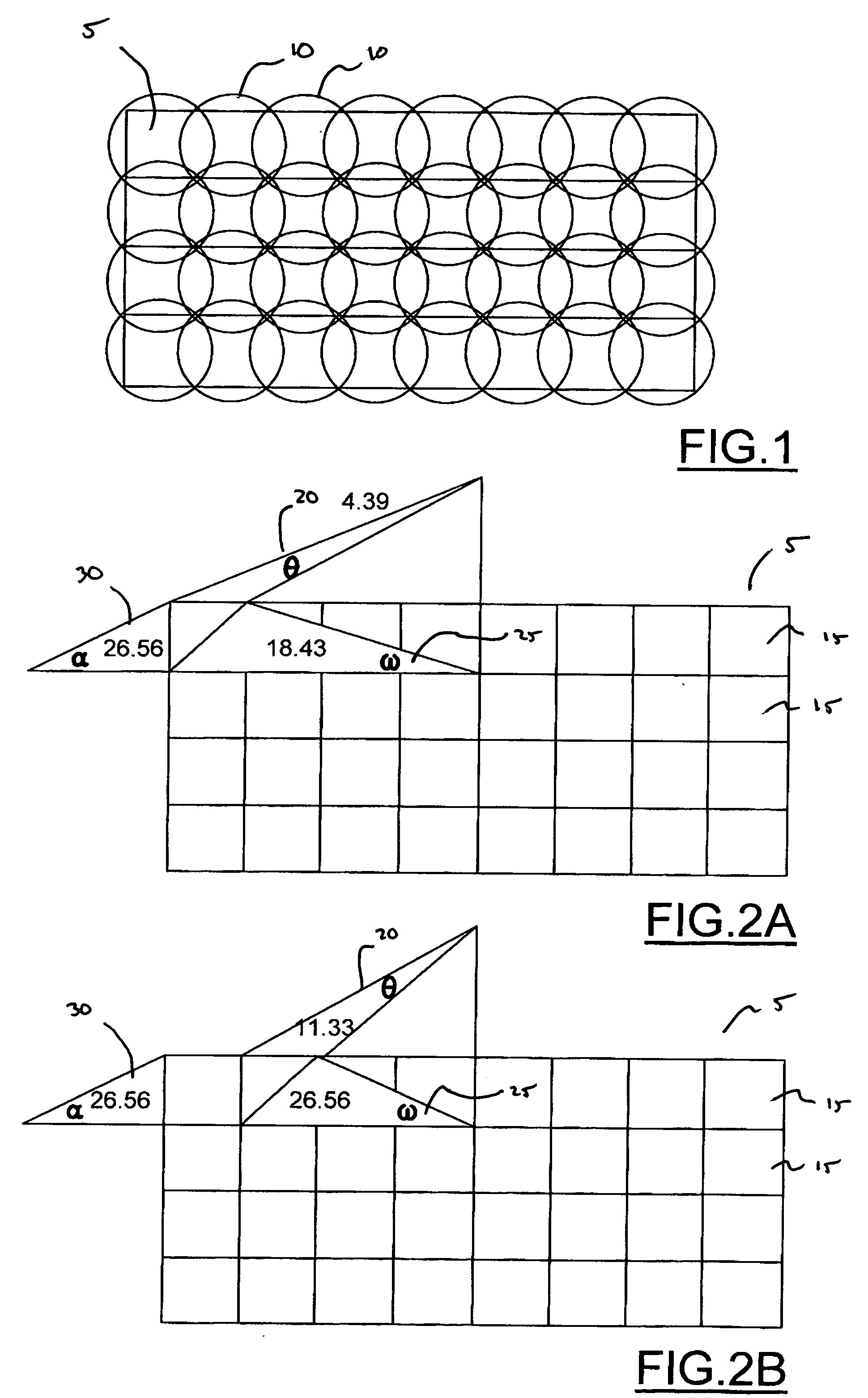
[0010] Referring to FIG. 1, there is shown a depiction of an area 5 to be lit by an illumination device with circular patterns 10 disposed thereon, representing circular light beams from the illumination device. The circular patterns 10 of light overlap each other to form a basically uniform pattern of illumination on the area to be lit. Such an arrangement of light beams provides a relatively uniform distribution of light over a relatively large area.

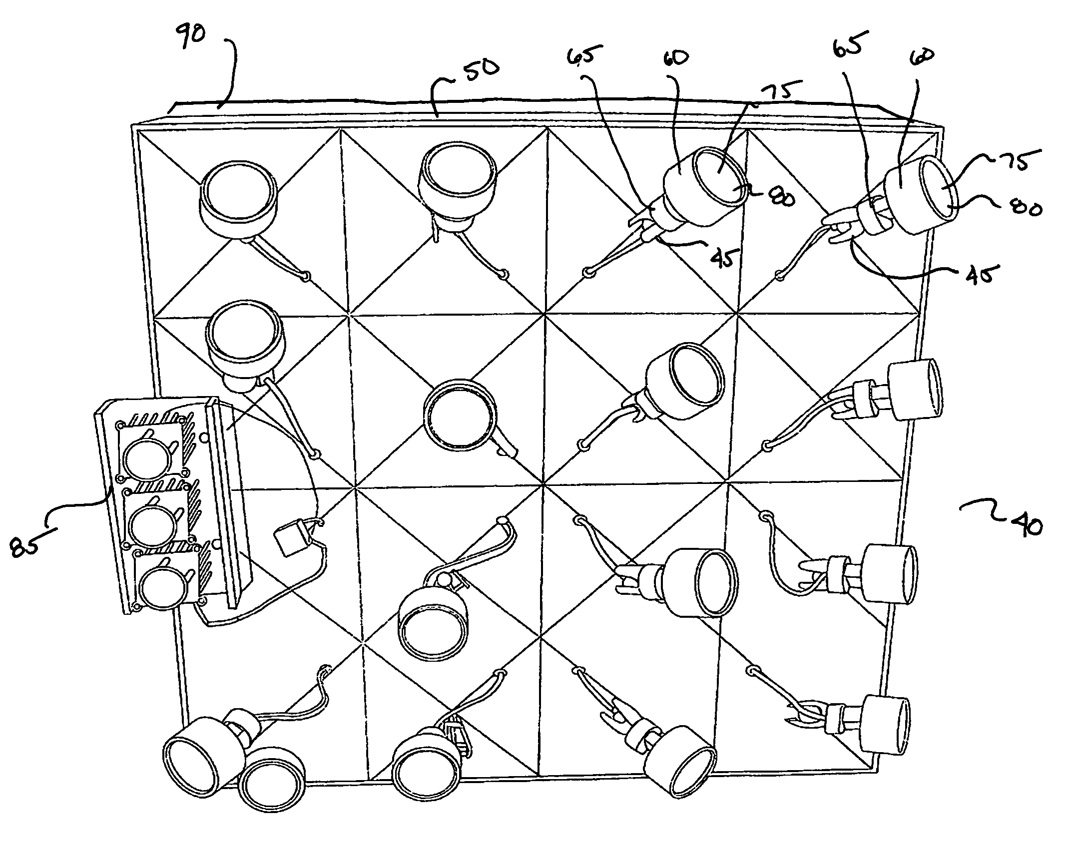
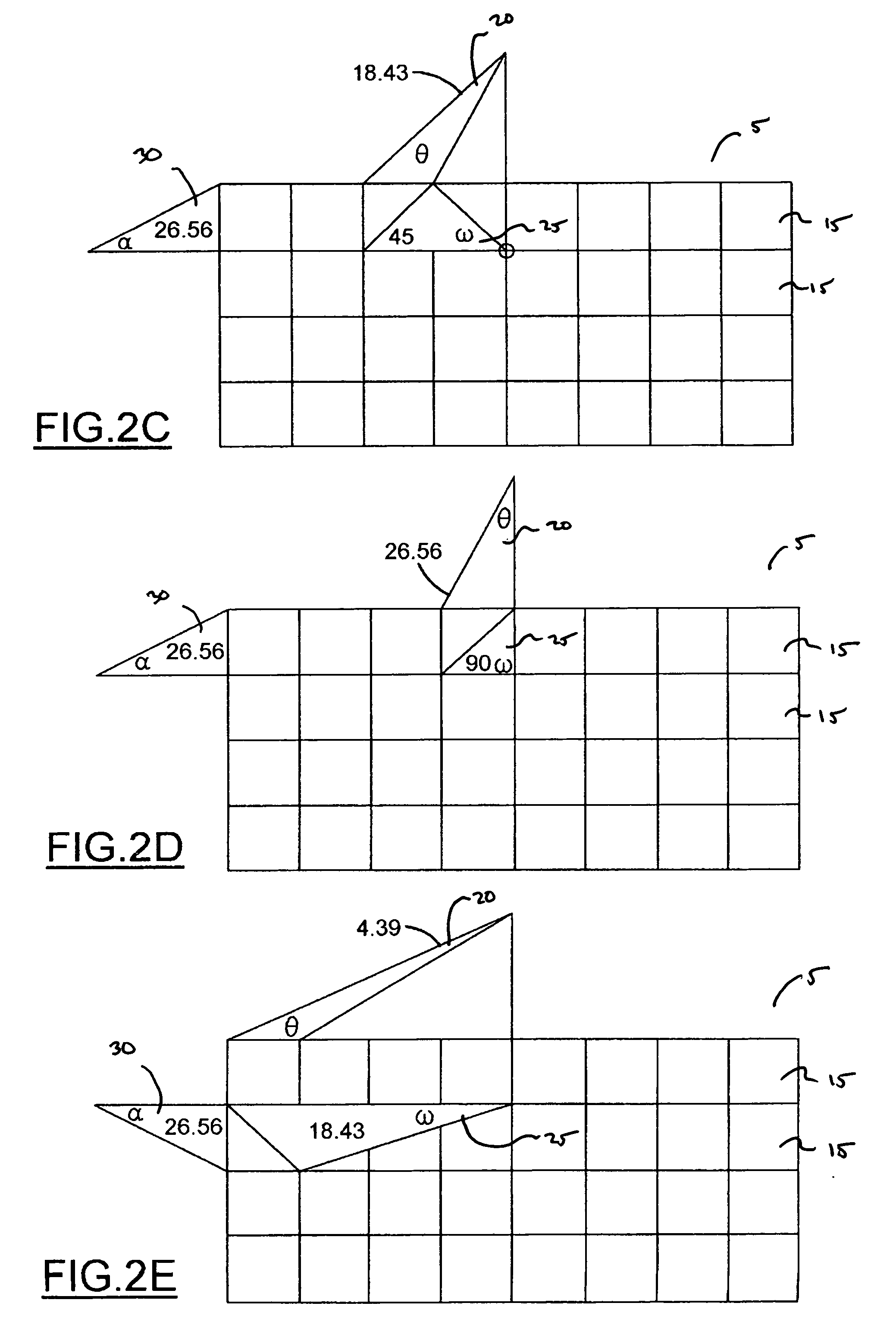
[0011]FIGS. 2A-2P illustrates the area 5 to be lit of FIG. 1 divided into grids 15. The illustrated grid of FIG. 2 is a 4×8 array of equal area grids. Each of the figures includes three angles from a solid-state light source. A first angle, theta 20, represents the vertical angle of the light source relative to the grid section 15. A second angle, omega 25, represents a horizontal angle of the light source relative to the grid section 15. A third angle, alpha 30, represents a depth angle of the light source relative to the grid sectio...


PUM


Abstract

A solid-state lighting array for illuminating a predefined area includes a support member. A plurality of solid-state light-emitting devices is supported on the support member so that each device projects an essentially circular pattern of illumination onto the predefined area. At least a portion of the plurality of light-emitting devices is disposed so as to project a beam of light onto the predefined area at an oblique angle. The portion of obliquely angled devices have an astigmatic lens associated therewith so that the pattern of illumination incident upon the surface of the predefined area is essentially circular.

Description

FIELD OF THE INVENTION [0001] This invention relates to illumination devices and more with more particularity to illumination devices having solid-state light emitting members. BACKGROUND OF THE INVENTION [0002] Solid-state light-emitting devices, such as light-emitting diodes, electroluminescent devices, solid-state lasers, and the like, secure a number of advantages over prior devices, such as incandescent lamps and fluorescent lamps, as light sources for illuminating relatively large areas. Solid-state devices are generally very energy efficient, and have a very long service life. Furthermore, production techniques have greatly increased the reliability of these devices, while decreasing their cost. Consequently, solid-state light-emitting devices are being utilized for lighting applications wherein relatively large areas, such as parking lots, transit shelters, advertising displays, and the like, are illuminated. The energy efficiency of these devices makes them particularly adv...

Claims


Application Information

Patent Timeline
IPC IPC(8): F21V21/00F21V15/00
CPCF21S2/00F21V21/29F21W2131/10F21Y2101/02F21Y2115/10
Inventor BEARS, JAMES
Owner SOLAR OUTDOOR LIGHTING
Why Eureka
Try Eureka