
Vertex reduction graphic drawing method and device

a graphic and drawing technology, applied in the field ofvertex reduction graphic drawing methods and devices, can solve the problems of spoiled graphic beauty and performance degradation in bird's eye view display, and achieve the effect of improving performan

Inactive Publication Date: 2006-07-06
FUJITSU MICROELECTRONICS LTD
View PDF1 Cites 79 Cited by
  • Summary
  • Abstract
  • Description
  • Claims
  • Application Information

AI Technical Summary

Benefits of technology

[0021] According to the present invention, performance can be improved by omitting vertices meaningless as an image due to too high density. Furthermore, by omitting some of vertices with too high density, a beautiful segment with uniform width and a beautiful polygon without ruined outlines can be obtained.

Problems solved by technology

The problem to be solved by the present invention is that performance degrades in a bird's eye view display and the beauty of a graphic is spoiled, since vertex density is too high.

Method used


Image

  • Vertex reduction graphic drawing method and device
  • Vertex reduction graphic drawing method and device
  • Vertex reduction graphic drawing method and device

Examples


Embodiment Construction

[0047]FIG. 5 shows the basic configuration of the vertex reduction graphic drawing device of the present invention. The present invention comprises features amount calculation unit 5 for calculating the amount of characteristic calculated, for example, based on the relative position of consecutive two vertices. For the amount of features, a straight distance between two vertices, horizontal and vertical distances between two vertices or the like are used.

[0048] The present invention further comprises a condition determination unit 6 for performing a conditional determination using the amount of features. For the condition determination, the fact that the straight distance between two vertices is equal to or less than a predetermined value, the fact that each of horizontal and vertical distances between two vertices is equal to or less than a predetermined value, the fact that the sum of horizontal and vertical distances between two vertices is equal to or less than a predetermined ...


PUM


Abstract

In a bird's eye view or the like, performance degrades due to a too high vertex density, and as a result, beauty is ruined. In order to solve such problems, an amount of features is calculated based on the relative position of the previously drawn vertex and a closely located vertex to it. Then, if the amount of features meets a specific threshold condition, the relevant vertex is eliminated from drawing targets, and a vertex the amount of features of which does not meet the threshold condition is specified as a subsequent drawing target.

Description

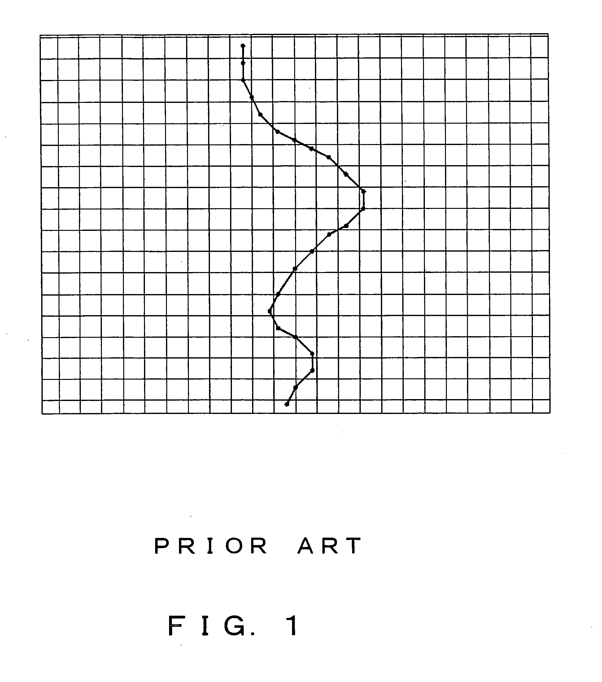
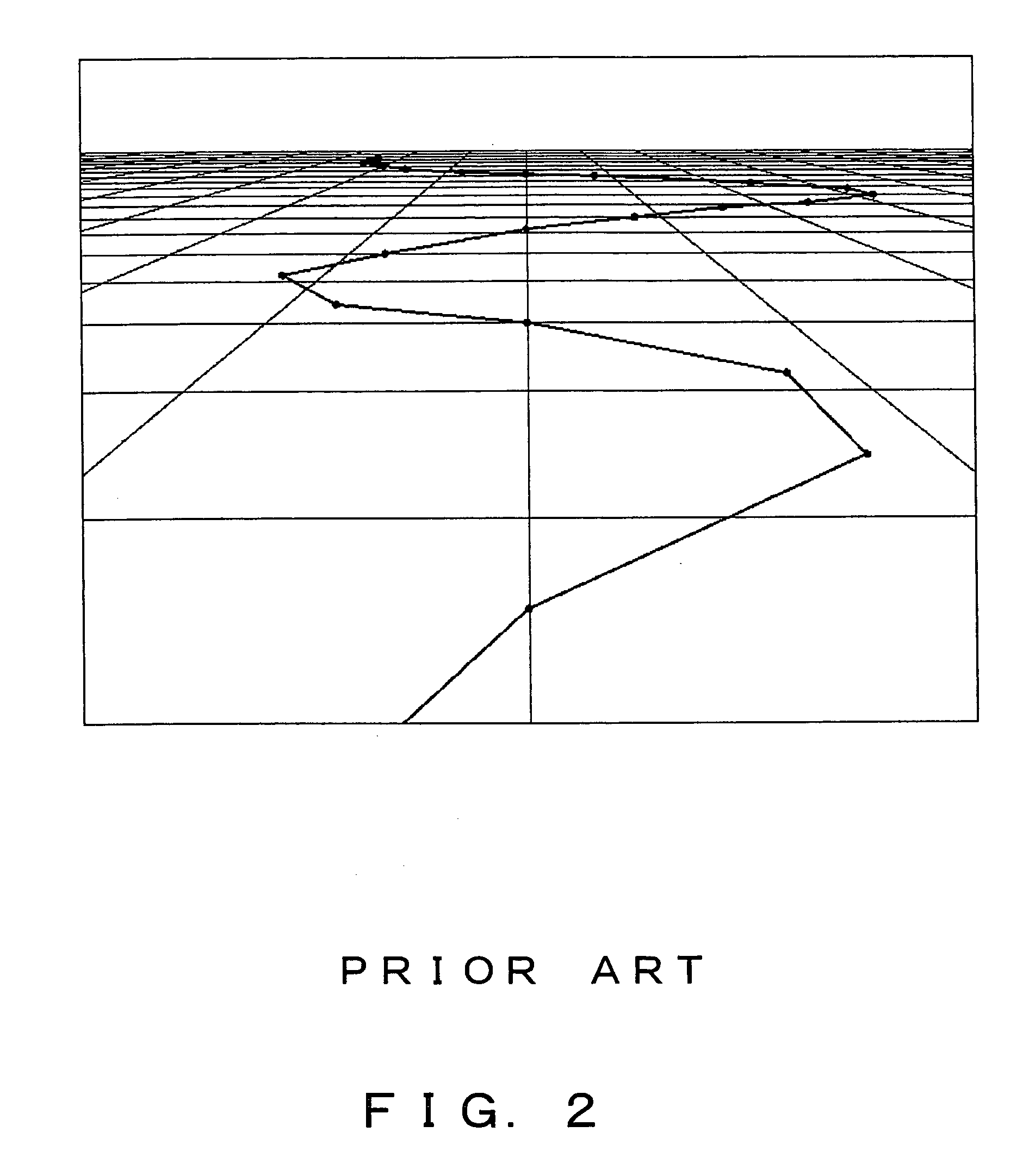
CROSS-REFERENCE TO RELATED APPLICATIONS [0001] This application is based upon and claims the benefit of priority from the prior JAPANESE Patent Application No. 2005-1025 filed on Jan. 5, 2005, the entire contents of which are incorporated herein by reference. BACKGROUND OF THE INVENTION [0002] 1. Field of the Invention [0003] The present invention relates to a device capable of connecting a plurality of vertex coordinates and drawing a polyline or a polygon. [0004] 2. Description of the Related Art [0005] In map drawing represented by, for example, a car navigation system, a process of providing a lot of vertex coordinates and drawing a polyline or a polygon is usually performed. As shown in FIG. 1, when a map is viewed from top and displayed two-dimensionally, vertex density is predictable beforehand, and the degree of details of a map database can be switched according to a reduced scale. However, if the map shown in FIG. 1 is inclined and displayed as a bird's eye view, as shown ...

Claims


Application Information

Patent Timeline
IPC IPC(8): G06T17/20G06T17/05
CPCG06T17/20
Inventor YAMAUCHI, HIDEAKI
Owner FUJITSU MICROELECTRONICS LTD
Learn More