Funnel for use in a cathode ray tube

a tunnel and cathode ray tube technology, applied in the manufacture electrical connections of cathode-ray/electron beam tubes, electrode systems, etc., can solve the problems of increasing the amount of glass gobs used, increasing manufacturing costs and the weight of glass bulbs, and improving mechanical strength of glass bulbs. , the effect of slimming down the cathode ray tub

Inactive Publication Date: 2006-07-06
SAMSUNG CORNING CO LTD
View PDF4 Cites 0 Cited by
  • Summary
  • Abstract
  • Description
  • Claims
  • Application Information

AI Technical Summary

Benefits of technology

[0009] It is, therefore, a primary object of the present invention to provide a funnel for use in a cathode ray tube, which is capable of achieving a weight reduction and slimming down of the cathode ray tube without changing a pin radius and a mold match line outside diameter, while satisfying an IEC (International Electrotechnical Commission) 16965 standard for implosion resistance by improving a mechanical strength of a glass bulb.

Problems solved by technology

However, if the funnel 30 is manufactured in such a manner that the deflection angle can be increased up to at least 120 degrees to slim down the cathode ray tube, this may raise a problem concerning the mechanical strength of the glass bulb 10 that is required to satisfy an IEC (International Electrotechnical Commission) 16965 standard for implosion resistance for the safety of users.
However, this solution leads to an increase in the amount of the glass gob used, which in turn results in raising the manufacturing costs and the weight of the glass bulb 10.
Furthermore, defects such as cracks and the like may be caused on the seal edge 34 because the flow rate of the glass gob increases at a time of press-forming the funnel 30.
So a great amount of time and costs are required for the plant and equipment investment.

Method used


Image

  • Funnel for use in a cathode ray tube
  • Funnel for use in a cathode ray tube
  • Funnel for use in a cathode ray tube

Examples


experimental examples

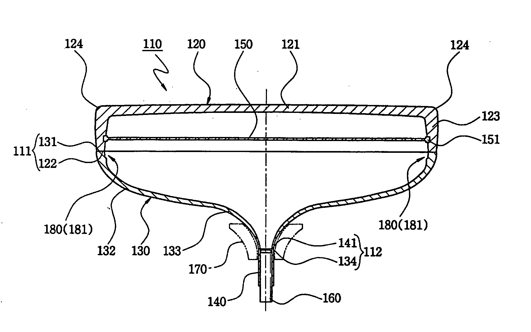
[0036] Weights (kg), stresses (MPa), incidence rates (%) of a seal edge crack, pin radii (mm) and mold match line outside diameters (mm) of funnels 130, each being formed to have the seal edge 131 with a thickness less than the thickness of the body portion 132, were measured, and the results are provided in Table 1. The kind of machine to which funnels in accordance with Example 1 and Comparative Examples 1 and 2 are employed is a 29-inch cathode ray tube, while the kind of machine to which funnels in accordance with Example 2 and Comparative Examples 3 and 4 is a 34-inch cathode ray tube.

[0037] In Table 1, the stresses (MPa) at a lower end portion of the seal edge 131 (hereinafter, simply referred to as seal edge lower end stress) were measured at a point spaced apart from the seal edge 131 by about 30 mm. Further, the pin radii (mm) in Table 1 represent a set of the pin radius d2 of the stud pin 151 installed at the skirt portion 123 along the direction of the minor axis 138, as...


PUM


Abstract

A funnel for use in a cathode ray tube having a panel includes a body portion having a seal edge to be connected to the panel and having a major axis of two longer sides of the body portion, a minor axis of two shorter sides of the body portion and diagonal axes; a yoke portion extending backward from the body portion; and an inflection portion formed on at least one portion of an inner surface of the body portion at a predetermined distance from the seal edge. The inflection portion is formed such that a thickness of the seal edge is less than that of the body portion.

Description

FIELD OF THE INVENTION [0001] The present invention relates to a funnel for use in a cathode ray tube; and, more particularly, to a funnel for use in a cathode ray tube which is capable of achieving a weight reduction and slimming down of the cathode ray tube without changing a pin radius and a mold match line outside diameter. BACKGROUND OF THE INVENTION [0002] A glass bulb employed in a cathode ray tube for use in manufacturing a color television, a computer monitor, and the like basically includes three main parts, i.e., a panel for displaying images thereon, a conical funnel connected to a backside of the panel and a cylindrical neck connected to the apex portion of the funnel. The panel, the funnel and the neck are formed of glass, and particularly the panel and the funnel are fabricated by press forming a lump of molten glass called a glass gob into desired sizes and shapes. [0003] A general configuration of a conventional cathode ray tube is illustrated in FIGS. 1 and 2. A pa...

Claims


Application Information

Patent Timeline
Patent Type & Authority Applications(United States)
IPC IPC(8): H01J29/86H01J61/30
CPCH01J9/244H01J9/40H01J29/86H01J29/861
Inventor AHN, IN HEEKIM, JUNG MOOK
Owner SAMSUNG CORNING CO LTD
Why Eureka
Try Eureka