
Cross-stacking container

a container and cross-stacking technology, applied in the field of containers, can solve the problems of increasing the volume of the conveyor, unable to allow the container, and the lack of versatility of the flat bottom, so as to avoid the hang-up of the container, increase the internal volume, and avoid the effect of increasing the weight of the container

Active Publication Date: 2006-07-06
SCHAEFER SUBCO LLC
View PDF9 Cites 17 Cited by
  • Summary
  • Abstract
  • Description
  • Claims
  • Application Information

AI Technical Summary

Benefits of technology

[0007] It is another object of the invention to provide a container that avoids container hang-up on a conveyor system.
[0008] It is another object of the invention to provide a container that has a greater internal volume than a flat bottom container of the same footprint without increasing the weight of the container.
[0009] It is another object of the invention to provide a container that reduces conveyor chatter caused by the interaction between the container and the conveyor system.
[0014] According to another preferred embodiment of the invention, the rim has a thickness substantially equal to the distance between an outside edge of the bottom wall and an outside perimeter of the base pad to provide a secure fit between stacked containers.

Problems solved by technology

Stackable containers having a flat bottom lack versatility and do not allow the containers to be stacked on top of multiple smaller containers.
Stackable containers having a molded grid pattern on the bottom tend to stick or hang-up on wheel-type conveyor systems, as well as, also producing an increased amount of conveyor chatter over that produced by a flat bottom container due to gaps between the ribs of the grid pattern which interact with the wheels of the conveyor system.

Method used


Image

  • Cross-stacking container
  • Cross-stacking container
  • Cross-stacking container

Examples


Embodiment Construction

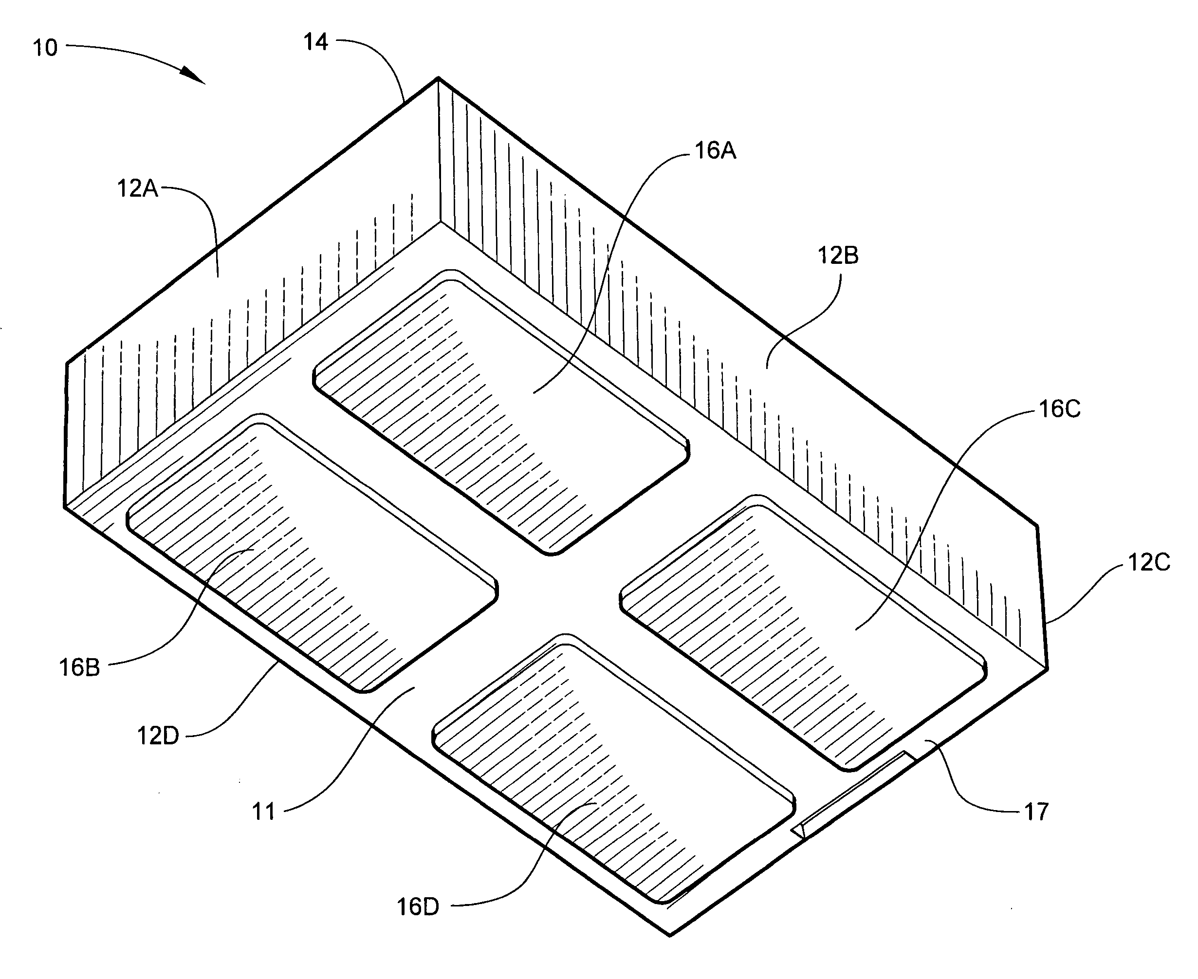
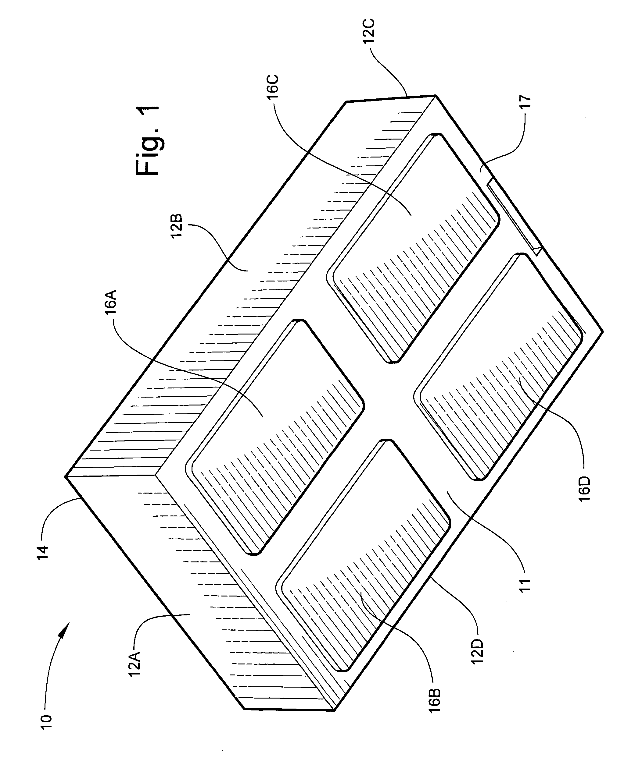
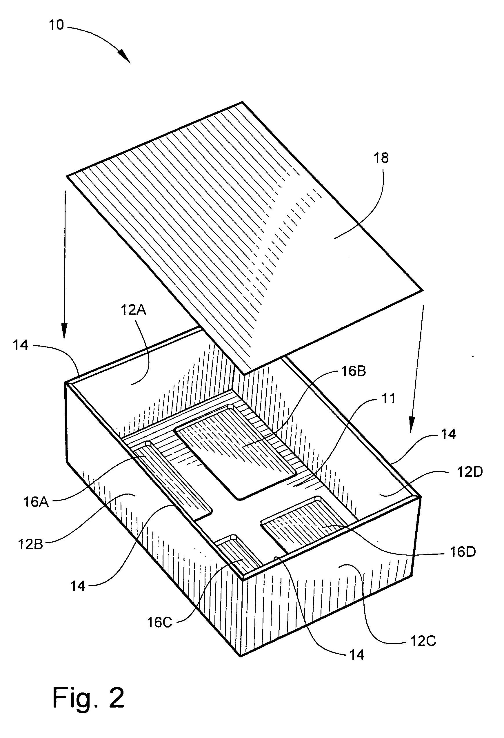
[0029] Referring now specifically to the drawings, a container according to an embodiment of the invention is illustrated in FIGS. 1 and 2 and shown generally at reference numeral 10.

[0030] The container 10 includes a bottom wall 11 and integrally-molded sidewalls 12A-12D. The sidewalls 12A-12D collectively define a rim 14 that extends around the perimeter of a top edge of the container 10 for supporting another container in a stacked configuration. The container 10 is made of a material suitable for supporting containers in a stacked configuration and for providing a long life cycle. In the illustrated example, the container 10 is made of a polyethylene plastic.

[0031] The interior side of the bottom wall 11 includes four molded-in recesses 16A-16D. The recesses 16A-16D preferably lack any reinforcing features such as a grid that would add tare weight or interfere with the ability of the recesses to furnish additional capacity. The container 10 thus holds a greater volume of mater...


PUM


Abstract

A stackable container that can be stacked with containers of various sizes, and that increases available storage volume without increasing weight. The stackable container includes a plurality of sidewalls and an integrally-formed bottom wall. The sidewalls have respective top edges which define a top opening and rim. At least one recess is formed in the bottom wall and extends exteriorly of the container beyond a plane of the bottom wall, and is defined by a perimeter support in the plane of the bottom wall. The recess is dimensioned for being received into a top opening of a second container with a rim of the second container being positioned on the perimeter support of the container for maintaining the container and the second container in stacked alignment with each other.

Description

TECHNICAL FIELD AND BACKGROUND [0001] This invention relates to a container, and more particularly, to a container including features permitting the container to be stacked with containers of other sizes and shapes. The containers described and claimed herein permit more efficient, compact utilization of space, particularly in assembly areas where consistent container size, position and orientation are important factors in assembly line efficiency. [0002] Stackable containers are well known in the art and come in all shapes and sizes. The regulatory weight limit for hand held containers has recently been reduced from 40 pounds to 35 pounds. Because of this reduction in hand held container weight limits, it has become more important for stackable containers to be as light as possible without sacrificing carrying capacity and versatility. [0003] It is common for stackable containers to have either a flat bottom or a bottom with an outwardly-projecting grid pattern molded onto the bott...

Claims


Application Information

Patent Timeline
IPC IPC(8): B65D21/00
CPCB65D21/0215B65D21/0235
Inventor MCDADE, CLINTON
Owner SCHAEFER SUBCO LLC
Learn More